4. Slide the hard disk drive cage into the opening in the front of the chassis till
half in.
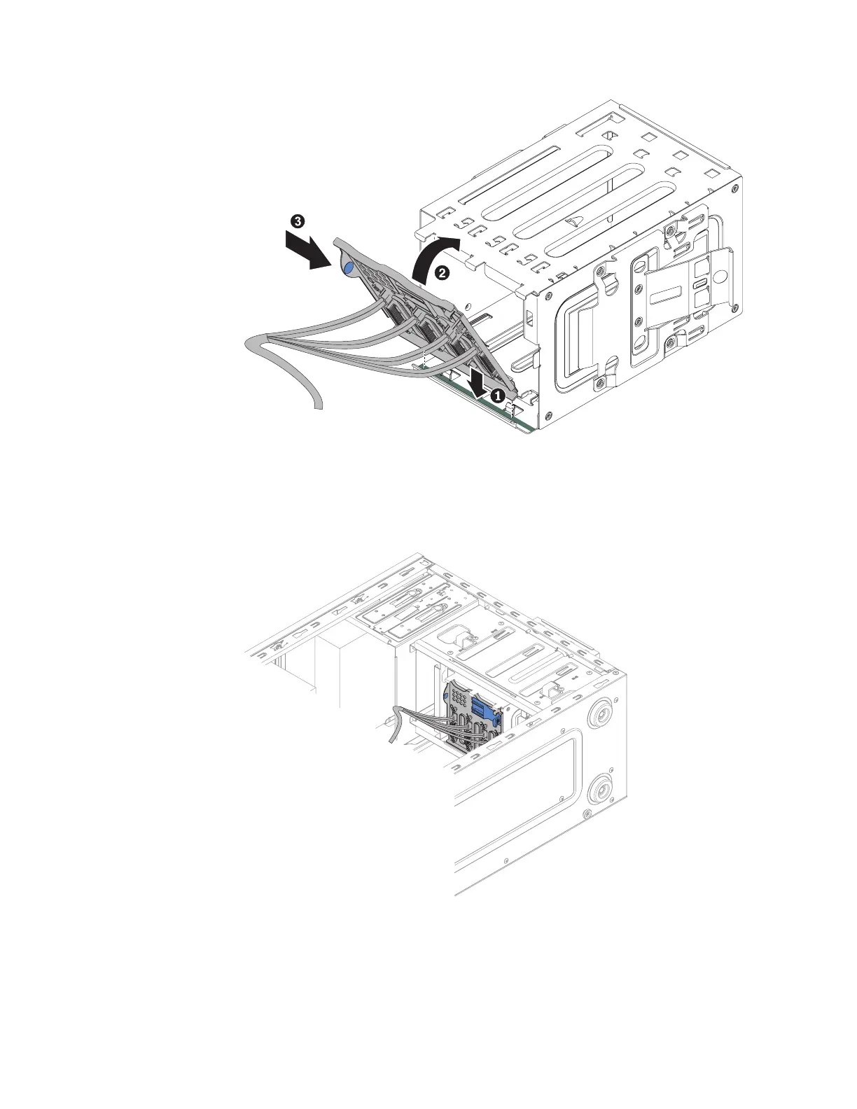
5. Connect the hard disk drive power cables to the backplate (connector P3 to
bay 3, connector P4 to bay 4, connector P5 to bay 5, and connector P6 to bay
6,).
Figure 141. Simple-swap backplate installation in hard disk drive cage for 4U server model
with non-hot-swap power supplies
Figure 142. Sliding hard disk drive cage half in into chassis for 4U server model with
non-hot-swap power supplies
Chapter 6. Removing and replacing components 235
 Loading...