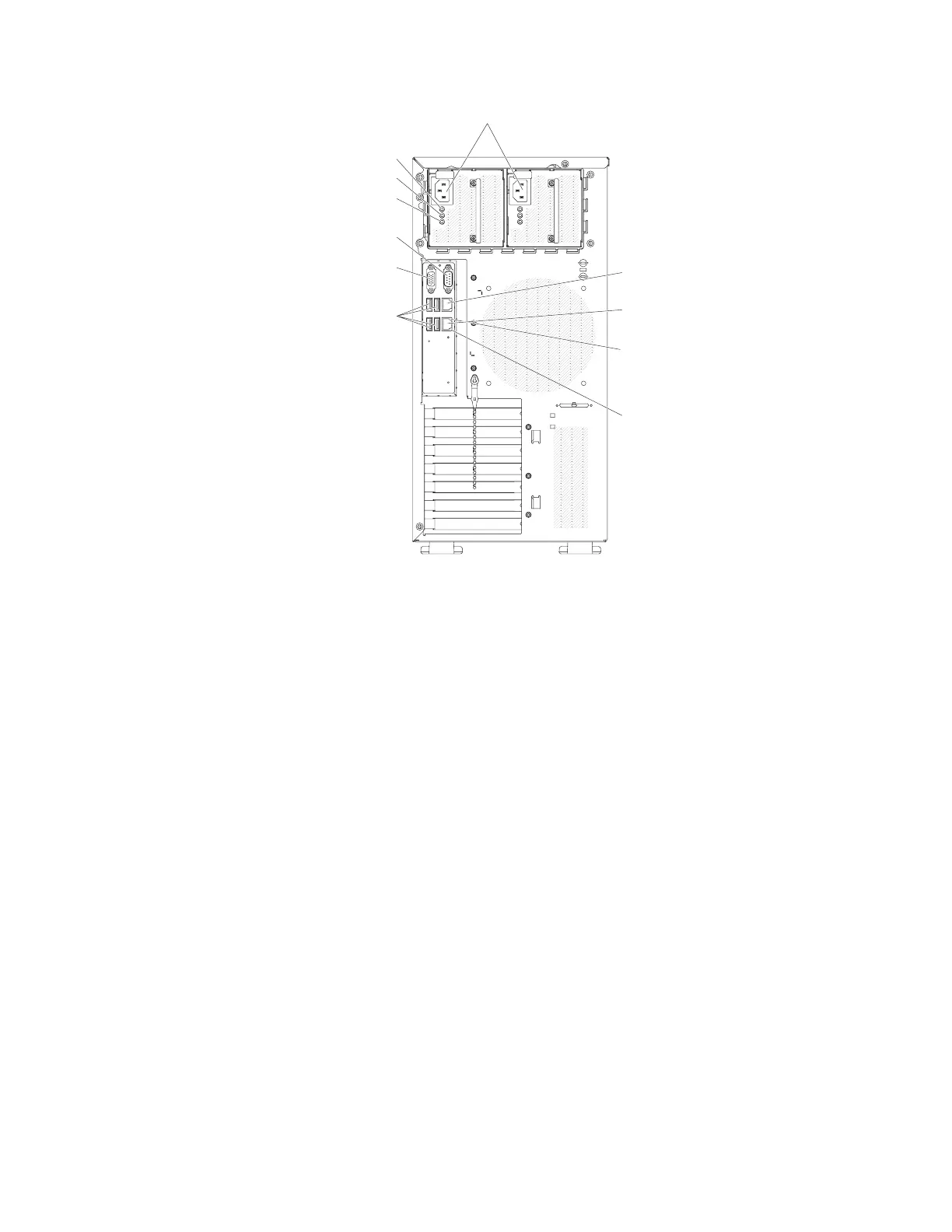
v Power connector: Connect the power cord to this connector.
v AC power LED: This green LED provides status information about the power
supply. During typical operation, both the ac and dc power LEDs are lit.
v DC power LED: This green LED provides status information about the power
supply. During typical operation, both the ac and dc power LEDs are lit.
v Fault-error LED: When this yellow LED is lit, it indicates that the power supply
has failed..
v Serial connector: Connect a 9-pin serial device to this connector. The serial port
is shared with the integrated management module II (IMM2). The IMM2 can
take control of the shared serial port to redirect serial traffic, using Serial over
LAN (SOL).
v Video connector: Connect a monitor to this connector.
v USB connectors: Connect USB devices to these connectors.
v NMI button: Press this button to force a nonmaskable interrupt to the
microprocessor. It allows you to blue screen the server and take a memory
dump (use this button only when directed by the IBM service support). You
might have to use a pen or the end of a straightened paper clip to press the
button.
v Ethernet connector: Use either of these connectors to connect the server to a
network. When you use the Ethernet 1 connector, the network can be shared
with the IMM2 through a single network cable.
v Ethernet transmit/receive activity LED: This LED is on the Ethernet connector.
When this LED is flashing, it indicates that there is activity between the server
and the network..
v Ethernet link status LED: This LED is on the Ethernet connector. When this
LED is lit, it indicates that there is an active connection on the Ethernet port.
Video
Serial (Com1)
Ethernet
connector 2
USB connectors
AC Power LED (green)
DC power LED (green)
Fault (error)LED (yellow)
Power connectors
Ethernet transmit/
receive activity LED
Ethernet link
status LED
Ethernet
connector 1
Figure 11. Rear view of 5U server model with hot-swap power supplies
24 System x3100 M5 Type 5457: Installation and Service Guide
 Loading...