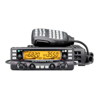
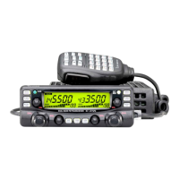
64
9
INSTALLATION AND CONNECTIONS
New2001
9
INSTALLATION AND CONNECTIONS
New2001
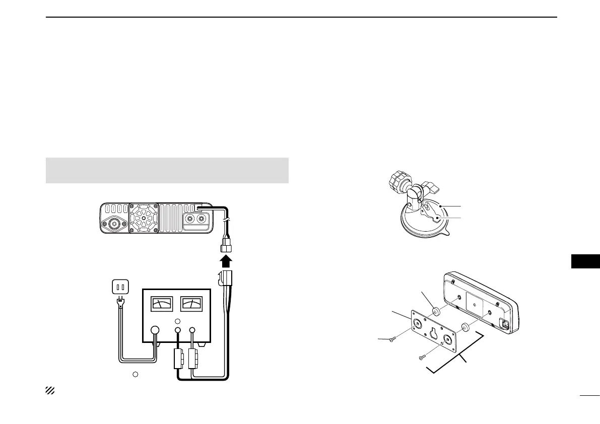
■ Connecting to a DC power
supply
Connect to a 13.8 V DC power source with at least 15 A ca-
pacity.
Connect the black DC power cable to the (–) Negative termi-
nal, and the red DC power cable to the (+) Positive terminal.
R WARNING! NEVER remove the fuse holders from the
DC power cable.
•CONNECTINGTOADCPOWERSUPPLY
⊕
−
Main unit
to an
AC outlet
DC power
supply 13.8 V
Fuses
15 A
−
⊕
Red Black
See page 69 for a car battery connection.
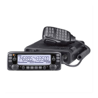
■ Installing the controller
D
When installing into your vehicle
You can install the controller on the dashboard or the console
of your vehicle with the optional MBA-5
c o n t r o l l e r b r a c k e t
and the MBF-1
m o u n t i n g b a s e . (p. 66)
Attach the MBF-1 on the dashboard or the console. q
•SeetheMBF-1instructionmanualfordetails.
MBF-1
Suction pad
Base lever
Attach the MBA-5 to the controller w ’s rear panel with the two
supplied screws as shown below.
Magnet
Controller
bracket
Screw
(M2.6×8)
MBA-5
 Loading...