11
2
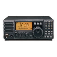
PANEL DESCRIPTION
!1 DATA TRANSMISSION SPEED INDICATOR
(p. 52)
Appears when 9600 bps speed is selected for pack-
et transmission.
!2 SPEECH COMPRESSOR INDICATOR (p. 36)
Appears when the speech compressor is activated.
!3 SET INDICATOR (p. 55)
Appears when [SET] is pushed.
Disappears after any switch is pushed.
!4 VOX INDICATOR (p. 33)
Appears when the VOX function is activated.
!5 SWEEP INDICATOR (p. 29)
Flashes while the simple bandscope function is ac-
tivated.
!6 SCAN INDICATOR (p. 46)
Flashes while scanning.
!7 NOISE REDUCTION INDICATOR (p. 31)
Appears when the optional DSP unit, UT-106, is in-
stalled and the noise reduction is activated.
!8 AGC TIME CONSTANT INDICATOR (p. 28)
Appears when the FAST AGC time constant is se-
lected; disappears when the SLOW AGC time con-
stant is selected.
!9 NOISE BLANKER INDICATOR (p. 30)
Appears when the noise blanker function is activat-
ed.
@0 AUTO FREQUENCY CONTROL INDICATOR
(p. 28)
Appears when the AFC (Automatic Frequency Con-
trol) function is activated.
@1 PRE-AMP INDICATOR (p. 16)
Appears when the optional pre-amplifier unit, AG-
25, AG-35 and/or AG-1200, is connected and the
pre-amplifier function is activated.
@2 ATTENUATOR INDICATOR (p. 29)
Appears when the attenuator is activated.
@3 MULTI-FUNCTION BAR METER
➥ Shows the receiving signal strength as an S-me-
ter while receiving. Peak hold function is avail-
able and can be switched ON and OFF in regular
set mode. (pgs. 26, 56)
➥ Shows the relative transmit output power level as
an RF power indicator during transmit. (p. 32)
➥ Shows signal availability in the sweeping band,
andthe“Z”indicatorindicatesthecenterofthe
sweeping frequency band.
@4 TONE SQUELCH INDICATOR (pgs. 30, 34)
“T”appearswhenthetoneencoderfunctionisacti-
vated;“T-SQL”appearswhenthetonesquelchfunc-
tion is activated.
@5 SUB INDICATOR (p. 19)
Appears when the SUB band access is enabled.
@6 SATELLITE INDICATOR (p. 49)
Appears while satellite operation mode is selected.
•
SATL
-
NOR
:Satelliteoperationwithnormalmode
is selected.
•
SATL
-
REV
:Satelliteoperationwithreversemode
is selected.
@7 REMOTE INDICATOR (p. 78)
Appears when the transceiver is controlled remote-
ly via the optional CI-V level converter, CT-17.
@8 LOCK INDICATOR (p. 25)
Appears when the dial lock function is activated.

 Loading...