72
11
OPTION INSTALLATIONS
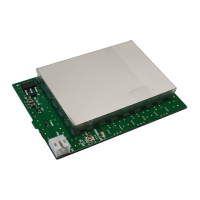
The UT-106 provides AF DSP functions such as noise
reduction and auto notch.
Up to 2 DSP units can be installed for simultaneous
DSP operation for both MAIN and SUB bands.
When only 1 DSP unit is installed, DSP functions can
be operated in either the MAIN or SUB band, whichev-
er is being accessed.
NOTE: The insulating soft case is not used with the
IC-910H.
RECOMMENDATION:
When installing only 1 DSP unit, you can install into
either front or rear panel side. However, installing a
DSP unit into the front panel side may be easier and
also safer.
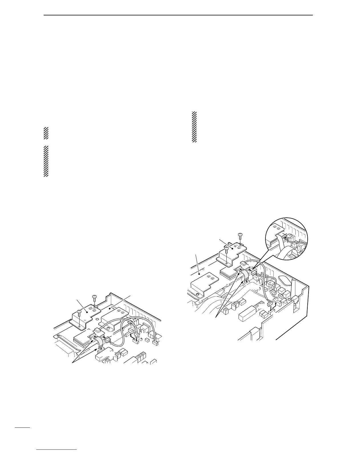
D
Installing 1st DSP unit (front panel side)
q Remove the top and bottom covers.
•RemovetheUX-910ifyouhaveinstalledit.(p.73)
w Remove the shielding plate.
e Remove the connection cable from J1751 on the
MAIN unit. Connect the cable into J1 on the UT-
106.
r Plug the connection cable (P1) from the UT-106 to
J1751 on the MAIN unit.
tPlug the at cableinto J3on the UT-106andto
J1771 on the MAIN unit.
•Takecareoftheconductordirection.
•Attach the Velcro tape to the UT-106 and PLL unit
shielding plate.
y Return the shielding plate, top cover and bottom
cover to their original positions.
D
Installing 2nd DSP unit (rear panel side)
q Remove the top and bottom covers.
•RemovetheUX-910ifyouhaveinstalledit.(p.73)
w Remove the shielding plate.
e Remove the connection cable from J1761 on the
MAIN unit. Connect the cable into J1 on the UT-
106.
The cable between J1221 on the MAIN and J1
on the DSP unit, must be set in the groove of the
chassis (see diagram below).
Otherwise, the cable may be damaged when re-
turning the shield plate to its original position.
r Plug the connection cable (P1) from the UT-106 to
J1761 on the MAIN unit.
tPlug the at cableinto J3on the UT-106andto
J1781 on the MAIN unit.
•Takecareoftheconductordirection.
•Attach the Velcro tape to the UT-106 and PLL unit
shielding plate.
y Return the shielding plate, top cover and bottom
cover to their original positions.

 Loading...