SECTION 3 INTERFACE INFORMATION
3-1
SECTION 3 INTERFACE INFORMATION
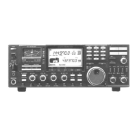
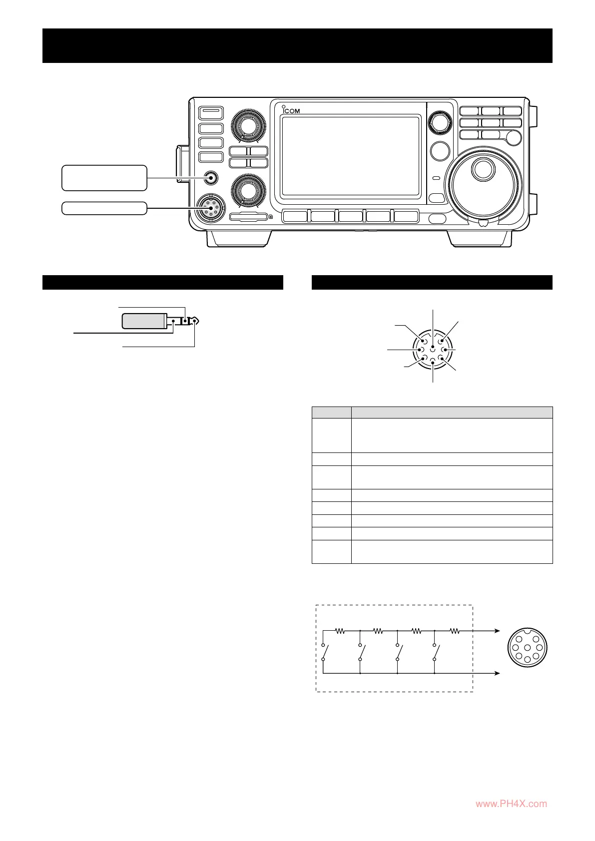
● FRONT panel
[PHONES]
• 3.5 mm (⅛ in) (d)
[MIC]
[PHONES]
Main band audio
Sub band audio
GND
3.5 (d) mm (⅛ in)
• Output impedance: 8 ~ 16 Ω
• Output level: More than 5 mW into an 8 Ω
load.
[MIC]
q Microphone input
w +8 V DC output
e Frequency up/down
r Squelch line output
t PTT
y GND (PTT ground)
i AF output
u GND
PIN No. DESCRIPTION
q
Microphone input
NOTE: This pin outputs 8 V DC power supply for
the Icom microphone.
w
+8 V DC output (Maximum 10 mA)
e
Frequency up/down
External keypad
*
input
r
Grounded when squelch opens.
t
PTT
y
PTT/External keypad
*
ground
u
Microphone ground
i
AF output [EXT-SP MAIN]/[EXT-SP SUB]
(varies with the AF control.)
*External keypad
PIN e
PIN y
1.5 kΩ
±5%
1.5 kΩ
±5%
2.2 kΩ
±5%
4.7 kΩ
±5%
S1S2S3S4
1
2
3
4
5
6
7
8
MIC
External keypad
Front panel
view
[MIC]
connector
www.PH4X.com
 Loading...