4-1
SECTION 4 ADJUSTMENT PROCEDURE
4-1 PREPARATION
■ REQUIRED EQUIPMENT
EQUIPMENT GRADE AND RANGE EQUIPMENT GRADE AND RANGE
DC power supply
Output voltage: 13.8 V±15%
Current capacity: 25 A or more
Shunt plug
Modified 3.5 mm (⅛ inch) monaural plug.
(See the illustration shown on page 4-2.)
RF power meter
(50 Ω terminated)
Measuring range: 1 ~ 120 W
Frequency range: 0.1 ~ 1500 MHz
SWR: Less than 1.2 : 1
Standard signal
generator (SSG)
Frequency range: 0.1 ~ 1500 MHz
Output level: −20 to 90 dBμ
(−127 to −17 dBm)
10 MHz reference
signal generator
Frequency accuracy: ±5×10
−4
ppm or less
Audio generator
(AG)
Frequency range: 300 ~ 3000 Hz
Output level: 1 ~ 500 mV
AC millivoltmeter Measuring range: 10 mV to 10 V Dummy Loads
Impedance: 100 Ω
Capacity: More than 120 W
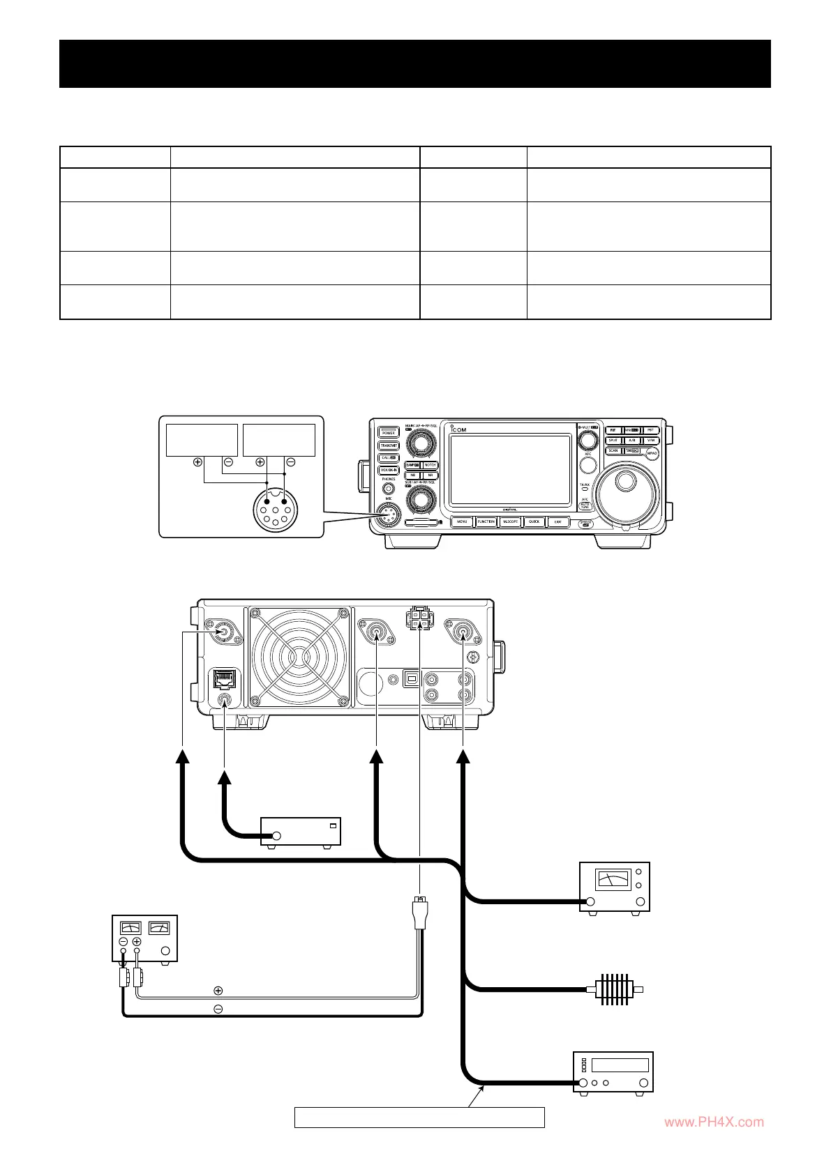
■ CONNECTIONS
● Connections on the Front panel
[MIC]
Audio
generator
[MIC]
MIC
MICE
AC
millivoltmeter
● Connections on the Rear panel
RF POWER METER
(120 W/50 Ω)
STANDARD SIGNAL GENERATOR
(0.1~1500 MHz)
NEVER TRANSMIT while the SSG is connected.
DUMMY LOAD
(100 Ω/120 W)
Used for SWR meter adjustments. (VSWR 2:1)
to [144MHz ANT] to [430MHz ANT]
to [REF IN 10MHz]
to [1200MHz ANT]
10 MHz REFERENCE
SIGNAL GENERATOR
(−10 dBm)
to [DC 13.8V]
DC POWER SUPPLY
(13.8 V/25 A)
Red
Black
www.PH4X.com
 Loading...