11
1
PANEL DESCRIPTION
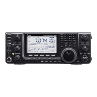
■ LCD display
q POWER DOWN TRANSMISSION ICON (p. 98)
Appears when the output power is decreased by
the Reduced Power Transmission function.
w TX ICON
Indicates the transmit frequency is displayed.
➥“
” appears while the operating frequency is in
an amateur band.
➥“ ” appears while the operating frequency
is not in an amateur band. However, when the
“Band Edge Beep” item is set to “OFF” in the Set
mode (p. 85), “ ” does not appear.
e RX ICON
Indicates the receive frequency is displayed.
r FREQUENCY READOUT
➥Displays the operating frequency.
•Whenthequicktuningicon“” is displayed, the fre-
quency changes in kHz quick tuning steps. (p. 27)
•Whenthequicktuningicon“” is not displayed, the
frequency changes in 10 Hz or 1 Hz steps.
➥When the Split function is ON, displays the re-
ceive frequency (VFO A or VFO B). (p. 66)
t MULTI-FUNCTION METER INDICATION
➥Displays the signal strength while receiving.
➥Displays the relative output power, ALC and
SWR or compression levels while transmitting.
(p. 33)
➥When the Meter Peak Hold function is ON, the
peak level of a received signal strength or the
output power is displayed for approximately 0.5
seconds. (p. 60)
y VOX ICON (p. 62)
Appears when the VOX function is ON.
u SPEECH COMPRESSOR ICON (p. 64)
Appears when the Speech Compressor function is
ON.
i FUNCTION DISPLAY (pp. 13, 14)
Shows the function of the
function switches ([F-1] to
[F-5]),
Set mode items and IF passband width.
o VOICE SQUELCH CONTROL ICON (p. 76)
Appears when the VSC (Voice Squelch Control)
function is ON.
!0 TONE SQUELCH ICONS
(Mode: FM)
➥“TONE” appears when the Repeater Tone func-
tion is ON. (p. 52)
➥“TSQL” appears when the Tone Squelch function
is ON. (p. 50)
!1 SPLIT READOUT (pp. 66, 67)
When the Split function is ON, displays the transmit
frequency (VFO A or VFO B).
!2 MEMORY CHANNEL READOUT (p. 69)
Displays the selected memory channel.
!3
SELECT MEMORY CHANNEL ICON (p. 80)
Appears when the selected memory channel is set
as a select memory channel.
!4 BLANK MEMORY ICON (pp. 69, 71)
Appears when the selected memory channel is
blank.
!5
1
⁄4 TUNING DIAL SPEED ICON (p. 27)
(Mode: SSB-D/CW/RTTY)
Appears when the tuning dial speed is set so that
one rotation is equal to
1
⁄4 of the normal rotation.

 Loading...