Draco U-Switch Table of Figures
65
16 Table of Figures
Fig. 1 System overview - Example direct source connection ................................................................. 11
Fig. 2 System overview - Example direct source connection with external switching solution ............... 12
Fig. 3 System overview - Example U-Switch in combination with KVM matrix switch............................ 12
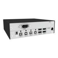
Fig. 4 Interface side chassis 474-BODY2 ............................................................................................... 16
Fig. 5 Interface side chassis 474-BODY2R ............................................................................................ 16
Fig. 6 Interface side chassis 474-BODY2N ............................................................................................ 17
Fig. 7 Interface side chassis 474-BODY2BPF ........................................................................................ 17
Fig. 8 Interface side chassis 474-BODY4 ............................................................................................... 17
Fig. 9 Interface side chassis 474-BODY4R ............................................................................................ 18
Fig. 10 Interface side chassis 474-BODY6R-R1 ...................................................................................... 18
Fig. 11 Interface side chassis 474-BODY6BP .......................................................................................... 19
Fig. 12 Rear view chassis 474-BODY6BP ................................................................................................ 19
Fig. 13 Interface side chassis 474-BODY6BPF ........................................................................................ 19
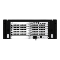
Fig. 14 Interface side chassis 474-BODY21/4U and 474-BODY21/4U .................................................... 20
Fig. 15 Rear view chassis 474-BODY21/4U and 474-BODY21/4U .......................................................... 20
Fig. 16 Interface side U-Switch module B476-4U4T ................................................................................. 21
Fig. 17 Interface side R474-BGX .............................................................................................................. 21
Fig. 18 Interface side chassis 474-BODY2 - Status LED ......................................................................... 22
Fig. 19 Interface side chassis 474-BODY2R - Status LEDs ..................................................................... 22
Fig. 20 Interface side chassis 474-BODY2N - Status LEDs ..................................................................... 23
Fig. 21 Interface side chassis 474-BODY2BPF - Status LEDs................................................................. 24
Fig. 22 Interface side chassis 474-BODY4 - Status LEDs ........................................................................ 25
Fig. 23 Interface side chassis 474-BODY4R - Status LEDs ..................................................................... 25
Fig. 24 Interface side chassis 474-BODY6R-R1 - Status LEDs ............................................................... 26
Fig. 25 Interface side chassis 474-BODY6BP - Status LEDs ................................................................... 27
Fig. 26 Interface side chassis 474-BODY6BPF - Status LEDs................................................................. 28
Fig. 27 Rear view chassis 474-BODY6BPF - Status LEDs ...................................................................... 28
Fig. 28 Rear side chassis 474-BODY21/4U und 474-BODY21/4UR - Status LEDs ................................ 29
Fig. 29 Interface side U-Switch module B476-4U4T - Status LED ........................................................... 30
Fig. 30 Management software Menu structure ....................................................................................... 33
Fig. 31 Example of DIP switch settings ..................................................................................................... 34
Fig. 32 Management software .................................................................................................................. 36
Fig. 33 Management software KM-Switch MSC Configuration - Select KM-Switch ............................ 37
Fig. 34 Management software KM-Switch MSC Configuration - Multi-Screen Control Configuration
...................................................................................................................................................... 38
Fig. 35 Multi-Screen Control Configuration - Correct display arrangement ..................................... 39
Fig. 36 Multi-Screen Control Configuration - Wrong display arrangement ....................................... 39
Fig. 37 Example - Config.txt with parameter to activate the routing of USB ports 1 and 4 ...................... 41
Fig. 38 Example - Display arrangement with gap between the displays .................................................. 44
Fig. 39 Management software Flash Update ........................................................................................... 50
Fig. 40 Management software Flash Update - Select KM-Switch ......................................................... 50
Fig. 41 Management software Flash Update - Identify KM-Switch Type .............................................. 51
 Loading...