C13
1-18
C13
C33 C33
1-19
1-21
5
4
3
1
2
7
1
2
3
4
6
5
1-20
11 - IE
INSTALLERUSERTECHNICIAN
1.11 INDOOR INSTALLATION.
• Type C conguration, sealed chamber and
fan assisted.
Horizontal intake kits - exhaust Ø 60/100.
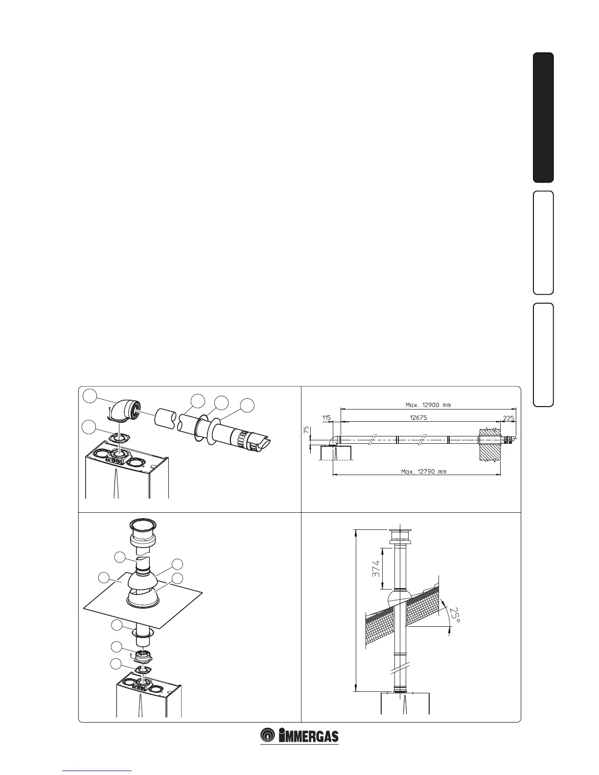
Kit assembly (Fig. 1-18): install the bend with
flange (2) on the central hole of the boiler,
positioning the gasket (1) (which does not
require lubrication). Position it with the circular
projections downwards in contact with the boiler
ange and tighten using the screws preset in the
kit. Fit the Ø 60/100 (3) concentric terminal pipe
with the male end (smooth) to the female end of
the bend (2) up to the stop; making sure that the
internal and external wall sealing plate have been
tted, this will ensure sealing and joining of the
elements making up the kit.
N.B.: for correct functioning of the system the
terminal with grid must be installed correctly
ensuring that, the "high" indication present on
the terminal is respected on installation.
• Coupling extension pipes and concentric
elbows Ø 60/100. To push-t extensions with
other elements of the ue extraction elements,
operate as follows Install the concentric pipe
or elbow with the male side (smooth) on the
female section (with lip seal) to the end stop
on the previously installed element. is will
ensure sealing and joining of the elements
correctly.
e kit Ø 60/100 can be installed with the rear,
right side, le side or front outlet.
• Extensions for horizontal kit (Fig. 1-19). e
horizontal intake-exhaust kit Ø 60/100 can
be extended up to a max. horizontal distance
of 12.9 m including the terminal with grid
and excluding the concentric bend leaving
the boiler. is conguration corresponds to
a resistance factor of 100. In these cases the
special extensions must be requested.
N.B.: when installing the pipes, a section clamp
with pin must be installed every 3 metres.
• External grill. N.B.: for safety purposes, do not
even temporarily obstruct the boiler intake-
exhaust terminal.
Vertical kit with aluminium tile Ø 60/100. Kit
assembly (Fig. 1-20): Install the concentric ange
(2) on the central hole of the boiler, positioning
the gasket (1) (which does not require lubrication)
with the circular projections downwards in
contact with the boiler ange and tighten using
the screws present in the kit.
Imitation aluminium tile installation: replace the
tile with the aluminium sheet (4), shaping it to
ensure that rainwater runs o. Position the xed
half-shell (6) and insert the intake-exhaust pipe
(5). Fit the Ø 60/100 (3) concentric terminal pipe
with the male end (5) (smooth) into the ange (2)
up to the stop; making sure that the wall sealing
plate has been tted (3), this will ensure sealing
and joining of the elements making up the kit.
Note: when the boiler is installed in areas where
very rigid temperatures can be reached, a special
anti-freeze kit is available that can be installed as
an alternative to the standard kit.
• Coupling extension pipes and concentric
elbows. To install push-fitting extensions
with other elements of the flue extraction
elements assembly, proceed as follows: Install
the concentric pipe or elbow with the male
side (smooth) on the female section (with lip
seal) to the end stop on the previously installed
element in order to ensure sealing eciency of
the coupling.
Important: if the exhaust terminal and/or
extension concentric pipe needs shortening,
consider that the internal duct must always
protrude by 5 mm with respect to the external
duct.
is specic terminal enables ue exhaust and
air intake, necessary for combustion, in a vertical
direction.
N.B.: e vertical kit Ø 60/100 with aluminium
tile enables installation on terraces and roofs
with maximum slope of 45% (25°) and the height
between the terminal cap and half-shell (374
mm) must always be respected. e vertical kit
with this conguration can be extended up to
maximum of 14.4 straight vertical m,including
the terminal. is conguration corresponds to
a resistance factor of 100. In this case the special
extensions must be requested.
e kit includes:
N° 1 - Gasket (1)
N° 1 - Concentric bend Ø 60/100 (2)
N° 1 - Concentric intake-exhaust terminal
Ø 60/100 (3)
N° 1 - Internal white wall sealing plate (4)
N° 1 - External grey wall sealing plate (5)
1-20
MAX. LENGTH 14400 mm
e kit includes:
N° 1 - Gasket (1)
N° 1 - Female concentric ange (2)
N° 1 - Wall sealing plate (3)
N° 1 - Aluminium tile (4)
N° 1 - Int./exhaust concentric pipe
Ø 60/100 (5)
N° 1 - Fixed half-shell (6)
N° 1 - Mobile half-shell (7)

 Loading...