(A)
(B)
1-121-11
8 - IE
INSTALLERUSERTECHNICIAN
1.8 IMMERGAS FLUE SYSTEMS.
Immergas supplies various solutions separately
from the boiler regarding the installation of air
intake terminals and ue exhaust; fundamental
for boiler operation.
Important: the boiler must be installed
exclusively with an original Immergas “Green
Range” air intake and flue gas extraction
system in plastic, as envisioned by Standards
in force.
e plastic pipes cannot be installed outdoors,
for tracts longer than 40 cm, without suitable
protection from UV rays and other atmospheric
agents.
This system c an be i dentif ied by an
identification mark and special distinctive
marking bearing the note: “only for condensing
boilers”.
• Resistance factors and equivalent lengths.
Each ue extraction system component has
a Resistance Factor based on experimental
tests and specified in the table below. The
resistance factor for individual components is
independent from the type of boiler on which
it is installed or the actual dimensions. It is,
however, conditioned by the temperature of the
uids that pass through the pipe and therefore
varies according to applications for air intake
or ue exhaust. Each individual component has
a resistance corresponding to a certain length
in metres of pipe of the same diameter; the
so-called equivalent length, obtained from the
ratio between the relative Resistance Factors.
All boilers have an experimentally obtainable
maximum Resistance Factor equal to 100.
The maximum Resistance Factor allowed
corresponds to the resistance encountered with
the maximum allowed pipe length for each
type of Terminal Kit. is information enables
calculations to verify the possibility of various
congurations of ue extraction systems.
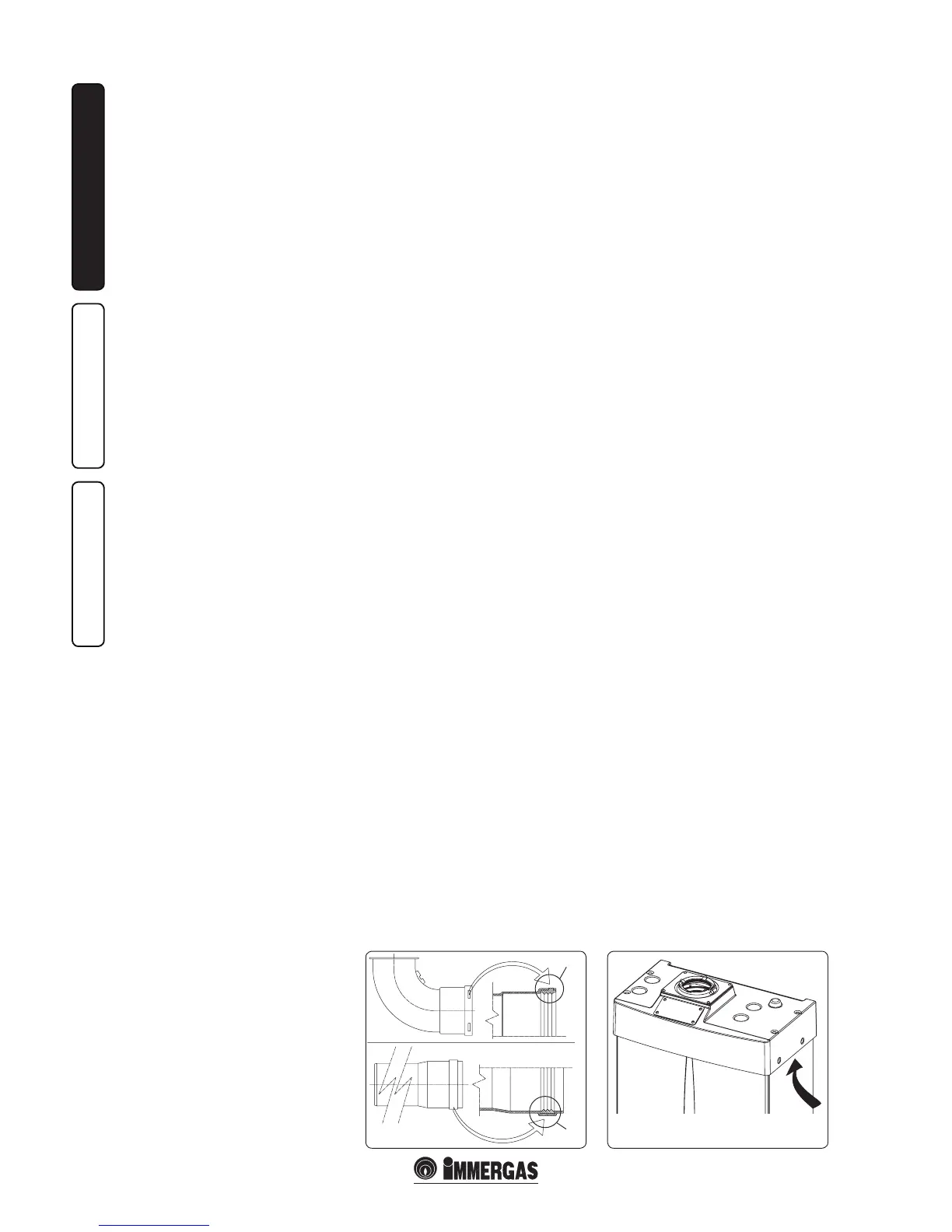
Positioning of the gaskets (black) for “green
range” ue extraction systems. Position the
gasket correctly (for bends and extensions)
(Fig. 1-11):
- gasket (A) with notches, to use for bends;
- gasket (B) without notches, to use for
extensions;
N.B.: if component lubrication (already carried
out by the manufacturer) is not sucient, remove
the residual lubricant using a dry cloth, then to
ease tting spread the elements with common
or industrial talc.
1.9 OUTDOOR INSTALLATION IN
PARTIALLY PROTECTED AREA.
N.B.: a partially protected area is one in which the
appliance is not exposed to the direct action of the
weather (rain, snow, hail, etc..)..
• Conguration type B, open chamber and
forced draught.
Using the relevant cover kit direct air intake is
possible (Fig. 1-12) and combustion products
are exhausted into a single ue or directly to the
outside. In this conguration it is possible to
install the boiler in a partially protected place.
In this conguration the boiler is classied as
type B
23
.
With this conguration:
- air intake takes place directly from the
environment in which the appliance is installed
(external);
- the ue exhaust must be connected to its own
individual ue or channelled directly into the
external atmosphere.
The technical regulations in force must be
respected.
• Cover kit assembly (Fig. 1-13). Remove the
two plugs and the gaskets present from the
two lateral holes with respect to the central
one. Now cover the right intake hole using the
relevant plate, xing it onto the le side using
the two previously-removed screws. Install the
Ø 80 outlet ange on the central hole of the
boiler, taking care to insert the gasket supplied
with the kit and tighten by means of the screws
provided. Install the upper cover, xing it using
the 4 screws present in the kit, positioning the
relevant gaskets. Engage the 90° Ø 80 bend
with the male end (smooth) in the female end
(with lip seal) of the Ø 80 ange unit until it
stops. Introduce the gasket, making it run along
the bend. Fix it using the sheet steel plate and
tighten by means of the straps present in the
kit, making sure to block the 4 gasket aps. Fit
the male end (smooth) of the exhaust terminal
into the the female end of the bend 90° Ø 80,
making sure that the relevant wall sealing
plate is already tted; this will ensure hold and
joining of the elements making up the kit.
Max. length of exhaust duct. The flue pipe
(vertical or horizontal) can be extended to a max.
length of 30 straight metres.
• Coupling of extension pipes. To install push-
tting extensions with other elements of the
flue extraction elements assembly, proceed
as follows: Couple the pipe or elbow with the
male side (smooth) in the female side (with lip
seal) to the end stop on the previously installed
element. is will ensure sealing eciency of
the coupling.
Example of installation with direct vertical
terminal in partially protected location. When
the vertical terminal for direct discharge of
combustion products is used, a minimum gap
of 300 mm must be le between the terminal
and the balcony above. e height X+Y+Z+W
evaluated with respect to the balcony above,
must be equal to or more than 2000 mm. (Fig.
1-15). e term W must only be considered if the
balcony above has closed balustrade (W=0 if the
balustrade is open).
• Conguration without cover kit in a partially
protected location (type C boiler)
By leaving the side plugs fitted it is possible
to install the appliance externally without the
cover kit. Installation takes place using the
Ø60/100 concentric intake/ exhaust kits. Refer
to the paragraph relative to indoor installation.
In this configuration the upper cover kit
guarantees additional protection for the boiler.
It is recommended but not compulsory.
1.10 OUTDOOR INSTALLATION USING
RECESS FRAME
WITH DIRECT AIR INTAKE
For this configuration, use the appropriate
spacers (included in the recess frame kit) and
place them under the side plugs of the sealed
chamber.
Air intake takes place directly from the external
environment (the recessed frame is thus
ventilated) and ue exhaust in single ue or
directly outdoors.
The boiler in this configuration, following
mounting instructions stated below, is classed
as type B
In this configuration, the flue exhaust must
be connected to its own individual flue or
channelled directly into the external atmosphere.
The technical regulations in force must be
respected.
Max. length of exhaust duct. The flue pipe
(vertical or horizontal) can be extended to a max.
length of 30 straight metres.

 Loading...