3-4
23 - IE
INSTALLERUSERTECHNICIAN
3.4 CONVERTING THE BOILER TO
OTHER TYPES OF GAS.
If the boiler has to be converted to a dierent gas
type to that specied on the data plate, request
the relative conversion kit for quick and easy
conversion.
Boiler conversion must be carried out by a
qualied technician (e.g. Immergas Technical
Assistance Service).
To convert to another type of gas the following
operations are required:
- remove the voltage from the appliance;
- replace the nozzle located between the gas pipe
and gas/air mixing sleeve (Part. 7 Fig. 1-28),
taking care to remove the voltage from the
appliance during this operation;
- apply voltage to the appliance;
- calibrate the number of fan revs. (Par. 3.5):
- adjust the correct air/gas ratio (Par. 3.6);
- seal the gas ow rate devices (if adjusted);
- aer completing conversion, apply the sticker,
present in the conversion kit, near the data-
plate. Using an indelible marker pen, cancel
the data relative to the old type of gas.
ese adjustments must be made with reference
to the type of gas used, following that given in
the table (Par. 3.19).
3.5 CALIBRATION OF NUMBER OF FAN
REVS.
Important: verification and calibration is
necessary, in the case of transformation to other
types of gas, in the extraordinary maintenance
phase with replacement of the circuit board,
air/gas circuit components or in the case of
installations with ue gas extraction systems,
with horizontal concentric pipe measuring more
than 1 metre.
The boiler heat output is correlated to the
length of the air intake and ue exhaust pipes.
is decreases with the increase of pipe length.
The boiler leaves the factory adjusted for
minimum pipe length (1m). It is therefore
necessary, especially in the case of maximum
pipe extension, to check the ∆p gas values aer at
least 5 minutes of burner functioning at nominal
heat output, when the temperatures of the intake
air and exhaust ue gases have stabilised. Adjust
the nominal and minimum heat output in the
domestic hot water and central heating modes
according to the values in the table (Par. 3.19)
using the dierential manometers connected to
the ∆p gas pressure point (15 and 16 Fig. 1-28).
Enter the congurations menu and regulate the
following parameters (Par. 3.8):
- DHW minimum power output;
- DHW maximum power output;
- minimum heating output;
- maximum central heating output;
- ignition power.
3.6 ADJUSTMENT OF THE AIRGAS
RATIO.
Important: the verication operations of the CO
2
must be carried out with the casing mounted,
while the gas valve calibration operations must
be carried out with the casing open and removing
the voltage from the boiler.
Calibration of the minimum CO
2
(minimum
heating power).
Enter the chimney sweep phase without
withdrawing domestic hot water and take the
selector switches to minimum (turn them in an
anti-clockwise direction until "0" is seen on the
display). to have an exact value of CO
2
in the ue
gases the technician must insert the sampling
probe to the bottom of the sample point, then
check that the CO
2
value is that specied in the
table, otherwise adjust the screw (3 Fig. 3-4) (O-
Set adjuster). To increase the CO
2
value, turn the
adjustment screw (3) in a clockwise direction and
vice versa to decrease it.
Calibration of the maximum CO
2
(nominal
central heating power).
On completion of the adjustment of the
minimum CO
2
keeping the chimney sweep
function active, take the heating selector switch
to maximum (turn it in a clockwise direction
until “99” is seen on the display). To have an exact
value of CO
2
in the ue gases the technician must
insert the sampling probe to the bottom of the
sample point, then check that the CO
2
value is
that specied in the table, otherwise adjust the
screw (12 Fig. 3-4) (Gas ow adjuster).
To increase the CO
2
value, turn the adjustment
screw (12) in an anti-clockwise direction and vice
versa to decrease it.
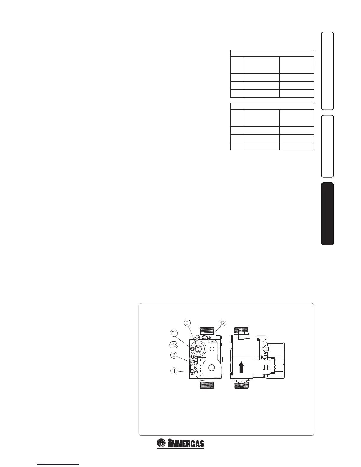
SIT 848 Gas Valve
Key:
1 - Gas valve inlet pressure point
2 - Gas valve outlet pressure point
3 - O/Set adjustment screw
12 - Outlet gas ow rate adjuster
At every adjustment variation on the screw 12 it
is necessary to wait for the boiler to stabilise itself
at the value set (about 30 sec.).
Victrix X 12 2I
CO
2
at nominal
output
(central heating)
CO
2
at minimum
output
(central heating)
G 20 9.50% ± 0.2 8.85% ± 0.2
G 30 12.50% ± 0.2 11.60% ± 0.2
G 31 10.60% ± 0.2 10.20% ± 0.2
Victrix X 24 2I
CO
2
at nominal
output
(central heating)
CO
2
at minimum
output
(central heating)
G 20 9.50% ± 0.2 8.9% ± 0.2
G 30 12.30% ± 0.2 11.60% ± 0.2
G 31 10.60% ± 0.2 10.20% ± 0.2
3.7 CHECKS FOLLOWING
CONVERSION TO ANOTHER TYPE
OF GAS.
Aer making sure that conversion was carried
out with a nozzle of suitable diameter for the
type of gas used and the settings are made at the
correct pressure, check that the burner ame is
not too high or low and is stable (does not detach
from burner);
N.B.:All boiler adjustment operations must
be carried out by a qualied technician (e.g.
Immergas Assistance Service).

 Loading...