1-8
1-7
1-9
1-10
45
31
58
1
2
7 - IE
INSTALLERUSERTECHNICIAN
1.6 REMOTE CONTROLS AND
ROOM CHRONOTHERMOSTATS
OPTIONAL.
e boiler is prepared for the application of room
chrono-thermostats or remote controls, which
are available as optional kits.
All Immergas chrono-thermostats are connected
with 2 wires only. Carefully read the user and
assembly instructions contained in the accessory
kit.
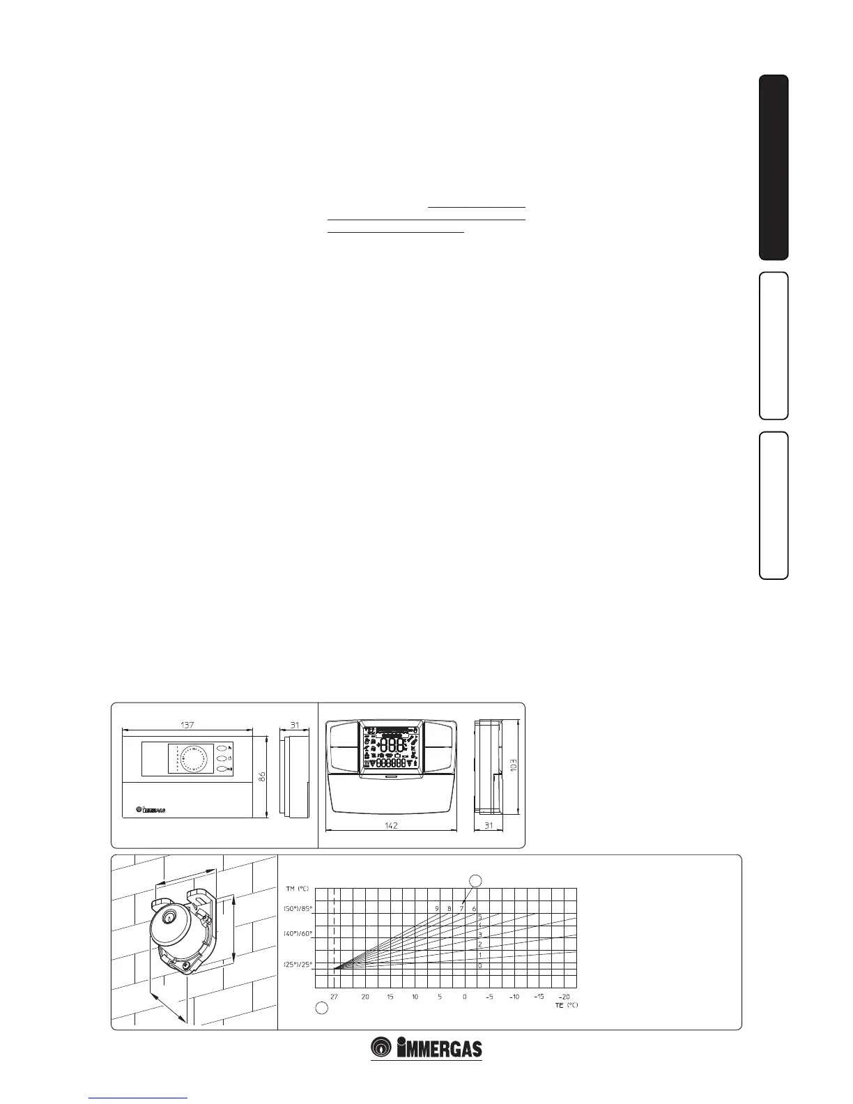
• On/O digital chrono-thermostat (Fig. 1-7).
e chrono-thermostat allows:
- to set two room temperature values: one for
day (comfort temperature) and one for night
(lower temperature);
- to set up to four on/o dierential weekly
programs;
- selecting the required function mode from
the various possible alternatives:
• permanent operation in comfort temp;
• permanent operation in lower temp;
• permanent operation in adjustable anti-freeze
temp.
e chrono-thermostat is powered by two 1.5V
LR 6 type alkaline batteries.
• Comando Amico Remoto Remote Control
Device
V2
CAR
V2
) (Fig. 1-8) with climate
chrono-thermostat function. In addition to
the functions described in the previous point,
the CAR
V2
panel enables the user to control all
the important information regarding operation
of the appliance and the heating system with
the opportunity of easily intervening on the
previously set parameters without having to
go to the place where the appliance is installed.
The Comando Amico Remoto
V2
Remote
Control panel is provided with self-diagnosis
to display any boiler operating anomalies.
e climate chrono-thermostat incorporated
into the remote panel enables the system ow
temperature to be adjusted to the actual needs
of the room being heated, in order to obtain
the desired room temperature with extreme
precision and therefore with evident saving
in running costs. It also allows to display the
eective room temperature and the external
temperature (if external probe is present).
e chrono-thermostat is fed directly by the
boiler by means of the same 2 wires used for
the transmission of data between boiler and
chrono-thermostat.
Important: if the system is divided into zones
using the relevant kit. the CAR
V2
must be used
with its climate thermostat function disabled, i.e.
it must be set to On/O mode.
CAR
V2
or chrono-thermostat On/O electric
connection (Optional). e operations described
below must be performed aer having removed
the voltage from the appliance. The eventual
On/O environment chrono-thermostat must
be connected to clamps 40 and 41 eliminating
jumper X40 (Fig. 3-2). Make sure that the On/
O thermostat contact is of the “clean” type,
i.e. independent of the mains supply, otherwise
the P.C.B. would be damaged. Any CAR
V2
must
be connected by means of terminals + and - to
clamps 41 and 44 on the P.C.B. (in boiler),
eliminating jumper X40 and respecting polarity
(Fig. 3-2). Connection with the wrong polarity
prevents functioning, but without damaging the
CAR
V2
e boiler can only be connected to one
remote control.
Important: If the CAR
V2
remote control is used,
arrange two separate lines in compliance with
current regulations regarding electrical systems.
No boiler pipes must ever be used to earth
the electric system or telephone lines. Ensure
elimination of this risk before making the boiler
electrical connections.
Installation with system operating at direct
low temperature. e boiler can directly feed a
low temperature system by acting on parameters
“S5” and S6” (par. 3.8). In this situation it is good
practice to insert a relevant safety kit (optional)
made up from a thermostat (with adjustable
temperature). e thermostat must be positioned
on the system ow pipe.
1.7 EXTERNAL PROBE OPTIONAL.
e boiler is prepared for the application of the
external probe (Fig. 1-9), which is available as an
optional kit. Refer to the relative instruction sheet
for positioning of the external probe.
The probe can be connected directly to the
boiler electrical system and allows the max.
system ow temperature to be automatically
decreased when the external temperature
increases, in order to adjust the heat supplied to
the system according to the change in external
temperature. e external probe always operates
when connected, regardless of the presence or
type of room chrono-thermostat used and can
work in combination with Immergas chrono-
thermostats. e correlation between system
ow temperature and external temperature is
determined by the position of the central heating
selector switch on the boiler control panel (or
on the CAR
V2
control panel if connected to the
boiler) according to the curves shown in the
diagram (Fig. 1-10). e electric connection of
the external probe must be made on clamps 38
and 39 on the terminal board positioned under
the sealed chamber (Fig. 3-2).
Key:
1 - Position of the central heating
temperature user adjustment
2 - In brackets, temperature
value with 25°/50° range
TM - Flow Temperature (°C)
TE - External Temperature (°C)

 Loading...