18 - IE
INSTALLERUSERTECHNICIAN
Each time the burner ignites, the relative ame
present symbol is displayed (10) with relative
power scale.
• Operation with Comando Amico Remoto
remote control
V2
(CAR
V2
) (Optional). If the
CAR
V2
is connected, the (
) symbol will
appear on the display. e boiler regulation
parameters can be set via the CAR
V2
control
panel and the reset button (3) remains active
on the boiler control panel, along with the
switch-o button (1) (“o” mode only) and the
display where the functioning state is shown
Important: if the boiler is put into "off "
mode, the “ERR>CM” connection error
symbol will appear on the CAR
V2
. e CAR
V2
is
however powered constantly so as not to loose
memorised programs.
• Solar functioning mode (
). is function
is activated automatically if the boiler detects
a probe on the DHW inlet (optional) or if the
“Solar ignition delay” parameter is more than
0 seconds.
During a withdrawal, if the outlet water is
hot enough, the boiler does not switch on,
the DHW withdrawal symbol (
) appears
on the display along with the ashing solar
function symbol (
).
When the water supplied by the solar system
is at a temperature lower than that at which
the boiler is set, the boiler switches on. At this
point, the solar function symbol will stay on
without ashing.
• Functioning with optional external probe
(
). In the case of a system with optional
external probe, the boiler ow temperature
for room central heating is managed by the
external probe depending on the external
temperature measured (Par. 1.6). The flow
temperature can be modied by selecting the
functioning curve via the selector switch (6)
(or on the CAR
V2
control panel, if connected
to the boiler) selecting a value from “0 to 9”.
With external probe present, the relative
symbol (18) will appear on the display. In the
central heating phase, if the temperature of the
water contained in the system is sucient to
heat the radiators, the boiler can only function
with the activation of the pump.
• “Stand-by” mode. Press button (1) in
succession until the (
) symbol appears.
e boiler remains inactive from this moment
and the anti-freeze function, pump anti-block
function and 3-way and signalling of any
anomalies is guaranteed.
N.B.: in these conditions the boiler is
considered still powered.
• “O” mode. By holding the button (1) down
for 8 seconds, the display switches-o and the
boiler is o completely. e safety functions are
not guaranteed in this mode.
N.B.: in these conditions the boiler is considered
still live even if there are no functions active.
• “Automatic vent” mode. Every time power is
supplied to the boiler. the system automatic
vent function is activated (duration 8 minutes).
This function is displayed via countdown
signalled by the indicator (14). During this
period the DHW and CH functions are not
active.
The “automatic vent” can be annulled by
pressing the “reset” button (4).
• Display functioning. e display lights up
during the use of the control panel, aer 15
seconds inactivity, the brightness drops until
just the active symbols are displayed. The
lighting mode can be varied via parameter t3
in the circuit board customisation menu.
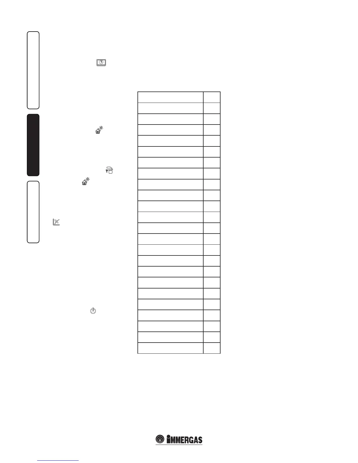
2.5 FAULT AND ANOMALY SIGNALS.
e Victrix 12 -24I boiler signals any anomalies
using a code shown on the boiler display (14)
according to the following table.
Anomaly signalled
Error
code
No ignition block 01
Safety thermostat block (over-
heating), ame control anomaly
02
Flue safety thermostat block 03
Contacts resistance block 04
Flow probe anomaly 05
Maximum N° of reset 08
Insucient system pressure 10
Storage tank probe anomaly
(optional)
12
Conguration error 15
Fan anomaly 16
Parasite ame block 20
Push button control panel anomaly 24
Block due to ue gas temperature
gradient intervention
25
Insucient circulation 27
Flue probe anomaly 29
Loss of remote control
communication
31
IMG Bus communication loss 36
Low power supply voltage 37
Loss of ame signal 38
Block due to loss of continuous
ame signal
43
Block for maximum time, partial
gas valve opening
44
Low temperature safety thermostat
(optional)
46
Burner power limitation 47
N.B.:on the Comando Amico Remoto
V2
remote
control (Optional), the error code corresponds
to the previous list with the “ERR>” indication in
front (E.g. code 01 CAR
V2
code ERR>01).
Ignition block. e boiler ignites automatically
with each demand for room central heating or
hot water production. If this does not occur
within the pre-established time, the boiler goes
into no ignition block. To eliminate “no ignition
block” the Reset button (3) must be pressed. On
commissioning or aer extended inactivity it
may be necessary to eliminate the “no ignition
block”. If this phenomenon occurs frequently,
contact a qualified technician for assistance
(e.g. Immergas Aer-Sales Technical Assistance
Service).
Safety thermostat block (over-heating), ame
control anomaly. During regular operation, if a
fault causes excessive overheating internally or
an anomaly occurs in the ame control section,
an overheating block is triggered in the boiler. To
eliminate “overheating block” the Reset button
(3) must be pressed. If this phenomenon occurs
frequently, contact a qualied technician for
assistance (e.g. Immergas Aer-Sales Technical
Assistance Service).
Flue safety thermostat block. is occurs in
the case of partial internal obstruction (due to
the presence of lime scale or mud) or external
blocking should occur (combustion residues)
to the condensation module. To eliminate the
“flue thermostat block” the Reset button (3)
must be pressed. Call an authorised technician
to remove the obstructions (e.g. Immergas Aer-
sales Service).
Contacts resistance block. is occurs in the
case of faults to the safety thermostat (over-
temperature) or anomaly in the ame control.
e boiler does not start and a technician must
be called (e.g. Immergas Aer-Sales Service).
System ow probe anomaly. If the board detects
an anomaly on the system NTC ow probe, the
boiler will not start; contact a qualied technician
for assistance (e.g. Immergas Aer-Sales Service).
Maximum N° of reset. To eliminate any
anomaly, the Reset button (3) must be pressed.
e Anomaly can be reset 5 times consecutively,
aer which the function in inhibited for at least
one hour. One attempt is gained every hour for
a maximum of 5 attempts.
Insucient system pressure. Water pressure
inside the central heating system that is sucient
to guarantee the correct functioning of the boiler
is not detected. Check on the boiler manometer
(7) that the system pressure is between 1÷1.2
bar and restore the correct pressure if necessary.
Storage tank probe anomaly (optional). If
the board detects an anomaly on the storage
tank probe, the boiler cannot produce DHW
and signals an anomaly; if necessary contact a
qualied technician for assistance (e.g. Immergas
Aer-Sales Technical Assistance Service).
Conguration error. If the board detects an
anomaly or incongruency on the electric wiring,
the boiler will not start. If normal conditions are
restored the boiler restarts without having to be
reset. If this anomaly persists, contact a qualied
technician for assistance (e.g. Immergas Aer-
Sales Service).
Fan anomaly. This occurs if the fan has a
mechanical or electrical fault. To eliminate the
“fan anomaly” the Reset button (3) must be
pressed. Call an authorised technician if the
anomaly persists (e.g. Immergas After-sales
Service).

 Loading...