C83
1-25
C43C53
1-241-23
1
4
7
9
5
5
6
7
8
3
2
S
A
12 - IE
INSTALLERUSERTECHNICIAN
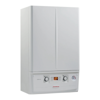
Separator kit Ø 80/80. e Ø 80/80 separator
kit, allows separation of the exhaust ues and
air intake pipes according to the diagram shown
in the gure. Combustion products are expelled
from pipe (S) (in plastic, so as to resist acid
condensate). Air is taken in through duct (A) for
combustion (this is also in plastic). e intake
pipe (A) can be installed either on the right or
le hand side of the central exhaust pipe (S). Both
ducts can be routed in any direction.
• Kit assembly (Fig. 1-23): install the ange (4)
on the central hole of the boiler, positioning the
gasket (1) (which does not require lubrication)
positioning it with the circular projections
downwards in contact with the boiler ange
and tighten using the hex screws with flat
end present in the kit. Remove the at ange
present in the lateral hole with respect to the
central one (according to needs) and replace it
with the ange (3), positioning the gasket (2)
already present in the boiler and tighten using
the supplied self-threading screws. Fit the male
end (smooth) to the bends (5) in the female end
of the anges (3 and 4). Fit the intake terminal
(6) with the male section (smooth) in the
female section of the bend (5) up to the stop,
ensuring that the internal and external wall
sealing plates are tted. Fit the exhaust pipe
(9) with the male end (smooth) to the female
end of the bend (5) up to the stop; making sure
that the internal wall sealing plate has been
tted, this will ensure sealing and joining of
the elements making up the kit.
• Coupling of extension pipes and elbows. To
install push-fitting extensions with other
elements of the flue extraction elements
assembly, proceed as follows: Install the pipe
or elbow with the male side (smooth) on the
female section (with lip seal) to the end stop
on the previously installed element. is will
ensure sealing and joining of the elements
correctly.
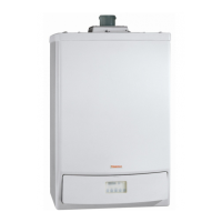
• Installation clearance (Fig. 1-24). e minimum
installation clearance measurements of the Ø
80/80 separator terminal kit have been stated
in some limit conditions.
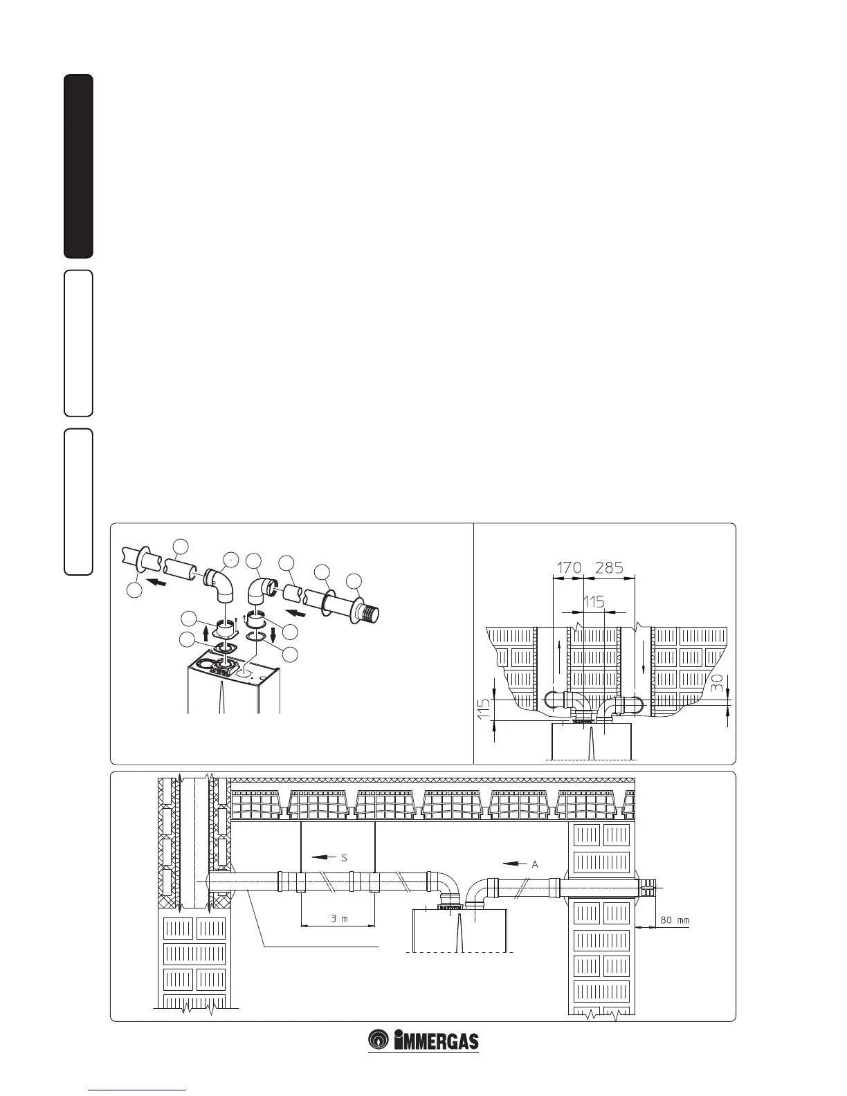
• Extensions for Ø 80/80 separator kit. The
maximum vertical straight length (without bends)
that can be used or Ø 80 intake and exhaust pipes
is 41 metres, independently to whether they
are used for intake or exhaust. e maximum
horizontal straight length (with bend in suction
and in exhaust) that can be used or Ø 80 intake
and exhaust pipes is 36 metres independently to
whether they are used for intake or exhaust.
N.B.: to favour the removal of possible condensate
forming in the exhaust pipe, tilt the pipes towards
the boilers with a min. slope of 1.5%. (Fig. 1-25).
When installing the Ø 80 ducts, a section clamp
with pin must be installed every 3 metres.
• Conguration type B
23
open chamber and
forced draught.
e appliance can be installed inside buildings in
B
23
mode; in this eventuality, all technical rules
and national and local regulations in force, must
be complied with.
e kit includes:
N° 1 - Exhaust gasket (1)
N° 1 - Flange gasket (2)
N° 1 - Female intake ange (3)
N° 1 - Female exhaust ange (4)
N° 2 - Bend 90° Ø 80 (5)
N° 1 - Intake terminal Ø 80 (6)
N° 2 - Internal white wall sealing plates (7)
N° 1 - External grey wall sealing plate (8)
N° 1 - Exhaust pipe Ø 80 (9)
- Type B open chamber boilers must not be
installed in places where commercial, artisan
or industrial activities take place, which use
products that may develop volatile vapours
or substances (e.g. acid vapours, glues, paints,
solvents, combustibles, etc.), as well as dusts
(e.g. dust deriving from the working of
wood, coal nes, cement, etc.), which may be
damaging for the components of the appliance
and jeopardise functioning.
- in type B
23
conguration, the boilers must not
be installed in bedrooms, bathrooms or in
bedsitters.
- The installation of appliances in B
23
conguration is only recommended outdoors
(in a partially protected place) or in places that
are not lived in and which are permanently
ventilated.
1.12 DUCTING OF FLUE TECHNICAL
SLOTS.
Ducting is an operation through which by the
introduction of one or more relevant pipes,
a system is realised for the evacuation of the
combustion products of a gas appliance made
up from the coupling of an existing or new
ducting pipe with a chimney, ue or technical
slot (also in new buildings) (Fig. 1-24). Ducting
requires the use of ducts declared to be suitable
for the purpose by the manufacturer, following
the installation and user instructions, provided
by the manufacturer and the requirements of
the standards.
Minimum slope 15%

 Loading...