3-1
21 - IE
INSTALLERUSERTECHNICIAN
3
BOILER
COMMISSIONING INITIAL
CHECK
To commission the boiler:
- ensure that the declaration of conformity of
installation is supplied with the appliance;
- ensure that the type of gas used corresponds to
boiler settings;
- check connection to a 230V-50Hz power
mains, correct L-N polarity and the earthing
connection;
- make sure the heating system is lled with
water and that the manometer indicates a
pressure of 1÷1.2 bar.
- switch the boiler on and ensure correct ignition;
- check the ∆p gas values in domestic hot water
and heating modes;
- check the CO
2
in the combustion products at
maximum and minimum ow rate;
- check activation of the safety device in the event
of no gas, as well as the relative activation time;
- check activation of the main switch located
upstream from the boiler and in the boiler;
- check that the intake and/or exhaust terminals
are not blocked;
- ensure activation of all adjustment devices;
- seal the gas ow rate regulation devices (if
settings are modied);
- check the production of DHW (when the boiler
is connected to an external cylinder unit);
- ensure sealing eciency of water circuits;
- check ventilation and/or aeration of the
installation room where provided.
If any checks/inspection give negative results, do
not start the boiler.
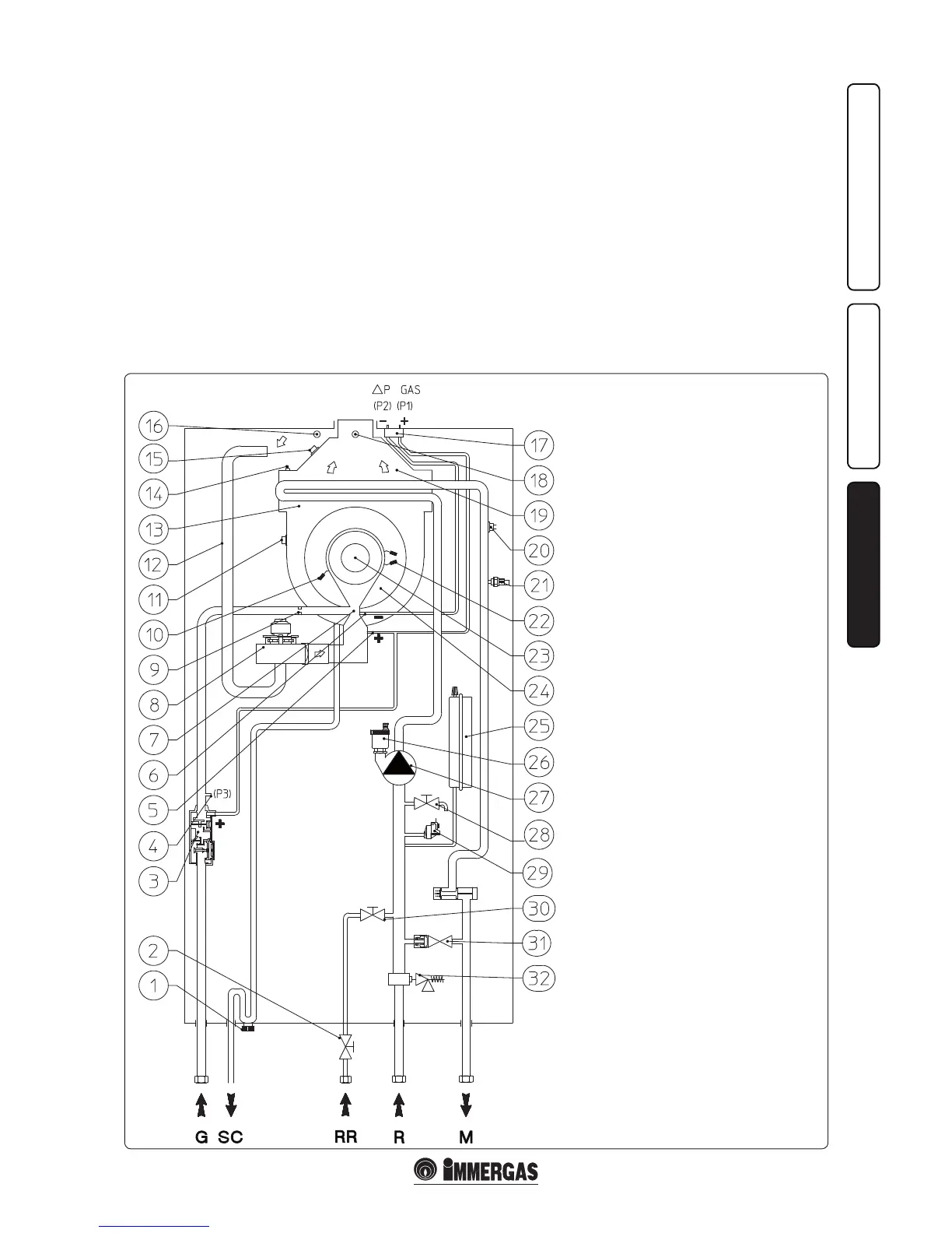
3.1 HYDRAULIC DIAGRAM.
Key:
1 - Condensate drain trap
2 - Filling cut-o valve
3 - Gas valve
4 - Gas valve outlet pressure point (P3)
5 - Venturi positive sign (P1)
6 - Venturi negative sign (P2)
7 - Air/gas Venturi manifold
8 - Fan
9 - Gas nozzle
10 - Detection electrode
11 - Flue probe
12 - Air intake pipe
13 - Condensation module
14 - Manual air vent valve
15 - Heat exchanger safety thermofuse
16 - Air sample point
17 - ∆p gas pressure point
18 - Flue sample point
19 - Flue hood
20 - Safety thermostat
21 - Flow probe
22 - Ignition electrode
23 - Burner
24 - Condensation module cover
25 - System expansion vessel
26 - Air vent valve
27 - Boiler pump
28 - System draining valve
29 - System pressure switch
30 - System lling valve
31 - By-pass
32 - 3 bar safety valve
G - Gas supply
SC - Condensate drain
RR - System lling
R - System return
M - System ow

 Loading...