12
2.5 ELECTRICAL INSTALLATION
Before proceeding further, we recommend that you
review the safety data in the front of this manual.
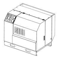
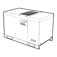
Locate the compressor data plate on the left end of
the cooler box next to the control box (See Figure
2.5-1).
The data plate lists the rated operating pressure, the
maximum discharge pressure, the electric motor char-
acteristics and power.
Confirm that the line voltage and compressor name-
plate voltage are the same.
The standard control box meets the intent of NEMA 1
guidelines.
It will be necessary to make a hole in the control box
for the incoming power connection. Care should be
taken to not allow metal shavings to enter the starter
and other electrical components within the box. After
making the power inlet hole, all shavings and debris
must be removed from inside of control box before
power is turned on.
Incoming power should be connected per the electri-
cal schematic at the rear of this manual (See Section
6.0). Confirm that all electrical connections are made
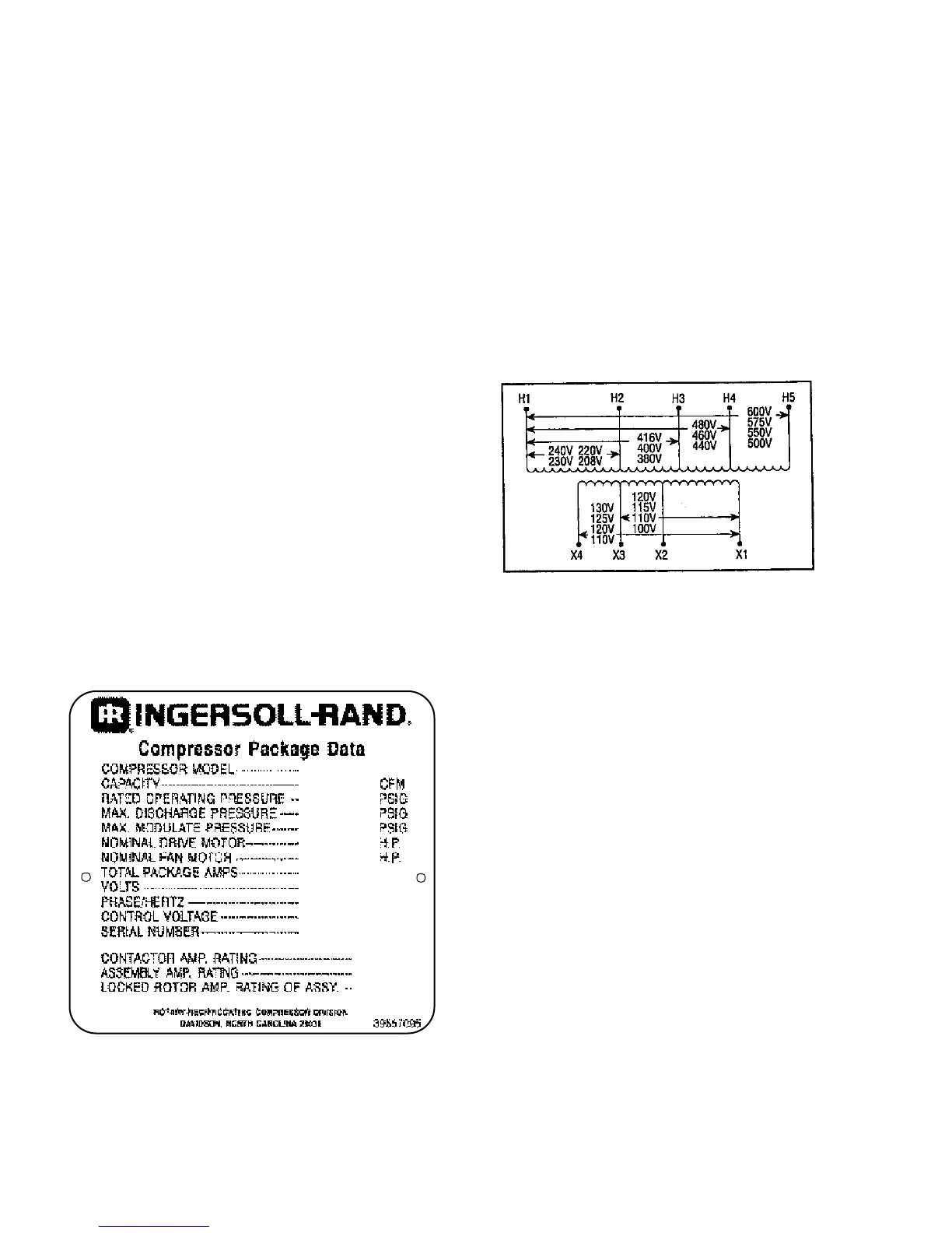
and tightened. Confirm that the control transformer is
wired correctly for supply voltage (See Figure 2.6-1).
FIGURE 2.6-1 CONTROL TRANSFORMER
CONNECTIONS
PRIMARY
SECONDARY
Inspect the motor and control wiring for tightness.
Replace control box door.
2.6 VOLTAGE CONVERSION
IMPORTANT:This procedure should only be carried out
by a qualified electrician, electrical contractor or your
local Ingersoll Rand Distributor or Air Center.
FIGURE 2.5-1 COMPRESSOR DATA PLATE
NOTE:This procedure applies only to units manufac-
tured to multi-voltage specifications. Compressor data
plate and motor nameplate must indicate multiple volt-
ages.
 Loading...