21
9. Remove seal housing from airend assembly. Use
the removal slots provided to pry the seal housing
from the airend. Do not attempt to break the seal
housing loose by tapping.
10. Drive each seal out of the housing, being careful
not to damage the surface of the bore.The larger
double lip seal must be driven out toward the
inboard side.The term “inboard” side of the seal
housing will refer to the face that is mounted to the
airend assembly.The term “outboard” side will refer
to the face closest to the sheave.
11. Discard seals.
12. Remove check valve ball and plug from seal
housing.
13. Remove wear sleeve from shaft, being careful
not to damage the shaft.
14.Thoroughly clean the scavenge holes, (See
Figure 4.8-1), bore surfaces of the seal housing,
wear sleeve journal on the shaft, and the face of the
airend assembly.Be careful not to damage any of
the surfaces, and insure that no particles are
allowed to enter the bearings.
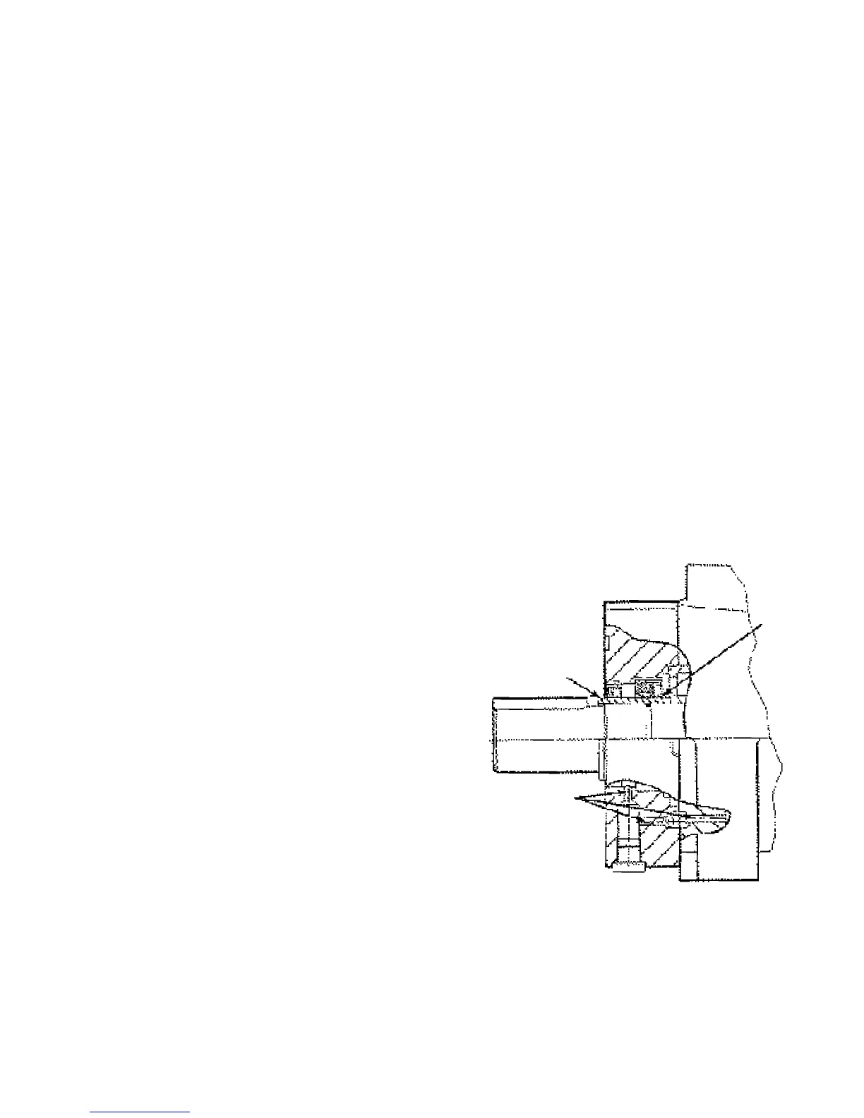
FIGURE 4.8-1 SHAFT SEAL ASSEMBLY
LIP EDGE
OF SEAL
INWARD
WEAR
SLEEVE
SCAVENGE
HOLES
4.8 SHAFT SEAL REPLACEMENT
There are two lip type seals on the compressor.They
are wearable parts and should be replaced at 8,000
hour intervals.While it is advisable to have your local
Ingersoll-Rand Distributor or Air Center perform this
work, the task can be accomplished by a good mechanic
following these instructions.
Before beginning any work on the compressor,
open, lock and tag the main electrical disconnect
and close the isolation valve on the compressor dis-
charge.Wait 2 minutes after stopping to allow inter-
nal pressure to dissipate.Vent residual pressure
from the unit by slowly unscrewing the coolant fill
plug one turn. Unscrewing the fill plug opens a vent
hole, drilled In the plug, allowing the pressure to
release to atmosphere (See Figure 4.3-1). A slight
mist or oil droplets may be visible during venting.
Do not remove fill plug until all pressure has vented
from the unit. Also vent piping by slightly opening
the drip leg valve.When opening the drain valve or
removing the coolant fill plug, stand clear of the
valve discharge, wear work gloves and appropriate
eye protection.
SPECIAL TOOLS
A clean work bench
Seal installation tool
REPLACEMENT PARTS
Shaft seal kit
Seal retainer 0-Ring
Loctite® 609
Loctite® 515
Installation
1. Remove the cooler box rear panel.
2. Remove belts (See Section 4.6).
3. Remove the three hex lead screws that hold the
sheave to the sheave bushing (See Figure 4.5-3).
4. Lubricate the thread and end of screws that were just
removed.
5. Reinstall all three screws in the holes of the bushing
that are threaded.
6. Slowly tighten the three screws evenly until the
sheave is pressed from the bushing. (Light tapping on
bushing may assist removal.)
7. Remove the screws from the holes.
8. Loosen allen screw in sheave bushing.
 Loading...