13
2.7 ROTATION CHECK.
Locate the rotation decal on the motor and check for
correct rotation.The correct rotation when viewed from
the opposite drive end of the motor is clockwise.
If compressor is operated in the opposite direction of
rotation, airend damage can result and is not war-
rantable.
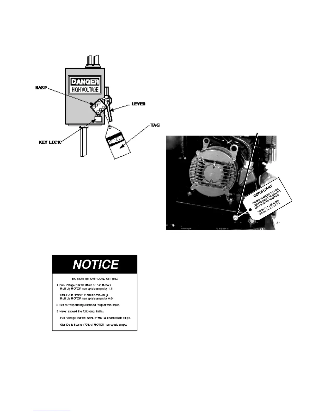
The unit is shipped with a bolt in the motor support to
prevent possible belt damage caused by bouncing dur-
ing shipment.This bolt must be remove prior to check-
ing motor rotation or operating the unit.
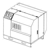
Locate the shipping bolt in the motor support as shown
in Figure 2.7-1. and remove.
For the compressor motor rotation check, the motor
jogging should be as short a time as possible.
1. Ensure that the Stop button is in the stop
(depressed) position.
2. Check coolant level.To check coolant level, slowly
loosen the fill plug one complete turn. As the fill plug is
unscrewed approximately one turn, a small amount of
pressure may be released. Do not remove the fill plug
until all pressure has been vented. Once pressure is
vented, finish removing the fill plug.The proper coolant
level is when the coolant is even with the top of the fill
port. Add coolant if necessary.
3. Replace and tighten fill plug.
4. Close the main disconnect switch (ON position).
5.Verify that the main isolation valve is open.
6. Open the canopy enclosure if machine is so
FIGURE 2.7-1 SHIPPING BOLT LOCATION
SHIPPING BOLT
PROCEDURE:
Put main disconnect in the OFF position, lock and tag
(See Figure 2.6-2).
Open the motor junction box on the side of the motor.
Reconnect the motor to the desired voltage. Use the
connection diagram provided on the motor as a guide.
Reconnect the primary side of the control transformer
for the desired voltage, as shown on the control trans-
former wiring decal.
Adjust motor overload setting as outlined below in
Figure 2.6-3.
FIGURE 2.6-3 MOTOR OVERLOAD SETTING
Make sure all wiring connections are tight.
Put main disconnect in the ON position and check
motor rotation, as outlined in Section 2.7 of this manu-
al.
FIGURE 2.6-2 MAIN DISCONNECT
LOCKED AND TAGGED
 Loading...