26
Before beginning any work on the compressor,
open, lock and tag the main electrical disconnect
and close the isolation valve on the compressor
discharge.Wait 2 minutes after stopping to allow
internal pressure to dissipate.Vent residual pres-
sure from the unit by slowly unscrewing the
coolant fill plug one turn. Unscrewing the fill plug
opens a vent hole, drilled in the plug, allowing the
pressure to release to atmosphere (See Figure 4.3-
1). A slight mist or oil droplets may be visible dur-
ing venting. Do not remove fill plug until all pres-
sure has vented from the unit. Also vent piping by
slightly opening the drip leg valve. When opening
the drain valve or removing the coolant fill plug,
stand clear of the valve discharge, wear work
gloves and appropriate eye protection.
Procedure:
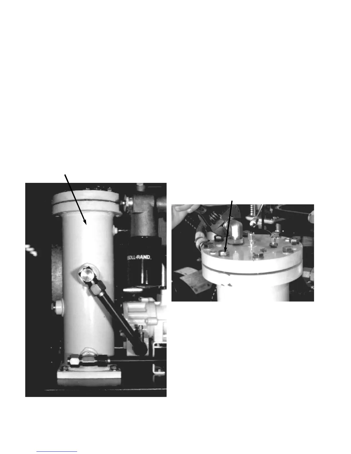
1. Disconnect tank discharge fitting, inlet valve control
tubing, and scavenge tube.
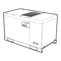
2. Remove tank cover bolts and cover (See Figure
4.13-2).
3. Remove separator element.
4. Clean all tank flange surfaces of dirt and residual
gasket material.
5. Install new separator element, making sure that the
grounding staple comes in contact with the flange
material.
FIGURE 4.13-2 TANK COVER REMOVAL
BOLT
Installation
Install the new hose. Refill the unit with coolant. Start
the compressor and check for leaks. Stop unit and
check coolant level in the sight glass on the separator
tank.
4.13 COOLANT SEPARATOR ELEMENT
The separator element should be replaced every year
or after 4000 hours of operation, whichever comes
first, to prevent excessive coolant carryover into the
plant’s air piping system.
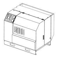
The element is located inside the separator tank (See
Figure 4.13-1).
FIGURE 4.13-1 SEPARATOR ELEMENT LOCATION
SEPARATOR ELEMENT (INSIDE)
 Loading...