20
4.6 DRIVE BELTS
Ensure that the compressor is isolated from the
compressed air system by closing the isolation
valve and venting pressure from the drip leg.
Ensure that the main power disconnect switch is
locked open and tagged.
If installing or removing the belts on a new unit at
startup, the motor support shipping bolt must first be
removed.This bolt is only used to secure the motor
support during shipment and will not be reinstalled
once the belts are put into place.
Locate the support shipping bolt as shown in Figure
2.7-1 and remove.
Replacement Parts
Belts (See Recommended Spare Parts Section 7.3).
Be sure to use only Ingersoll-Rand genuine parts to
assure proper belt size and length. Incorrectly sized
belts can lead to overloading of bearings and eventual
airend or motor failure.
Disassembly
Belt tension is maintained due to a pivoting motor
support.The weight of the motor holds the belt tight.
1. Remove the cooler box rear panel.
2. Carefully lift the back of the motor support and
place a block of wood underneath the motor support.
3. Remove belts from the airend sheave and the
motor sheave.
Installation / Inspection
Inspect sheave grooves for foreign material or rubber
build-up. Clean and degrease sheaves before
installing drive belts to insure long belt life.
1. Carefully lift the back of the motor support plate and
place a block of wood underneath the plate.
2. Install belts on the airend sheave and the motor
sheave.When installing a new belt, do not pry or force
the belt over the sheave grooves.
3. Remove the block of wood from under the motor
support.
4.7 BELTTENSION
This unit has been designed with a unique self ten-
sioning system for the drive belts.There is no adjust-
ment required to insure proper belt tensioning. Be
sure to use only Ingersoll-Rand Genuine parts to
assure correct belt tension.
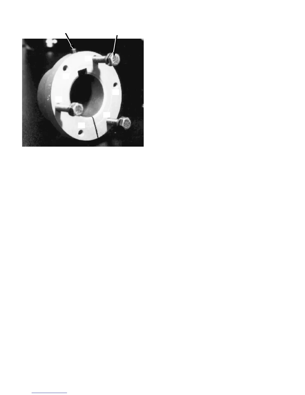
“A” - Clearance Holes
“B” - Threaded Holes
FIGURE 4.5-3 MOTOR SHEAVE BUSHING
7. Loosen allen screw in sheave bushing.
8. Move the bushing either in or out on the motor shaft
depending upon the measurement taken earlier.
9.Tighten allen screw in sheave bushing.
10. Being careful to not move the bushing on the shaft,
align sheave so that the three threaded holes in the
sheave line up with the three clearance holes in the
bushing.
11. Insert all three screws through clearance holes in
the bushing and thread into sheave.
12. Slowly and evenly tighten all sheave retaining
screws.Torque to 108 lb-in. (1.2 kg-m).
13.Tap against large end of bushing using hammer
and block or sleeve to avoid damage. Continue to
torque screws until the specified wrench torque no
longer turns the screw after tapping.
14. Install belts as shown in Section 4.6.
15. Recheck for proper alignment.
16. Reinstall cooler box outer panel.
ALLEN HEAD SCREW
SHEAVE RETAINING SCREWS
B
B
B
A
A
A
 Loading...