19
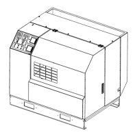
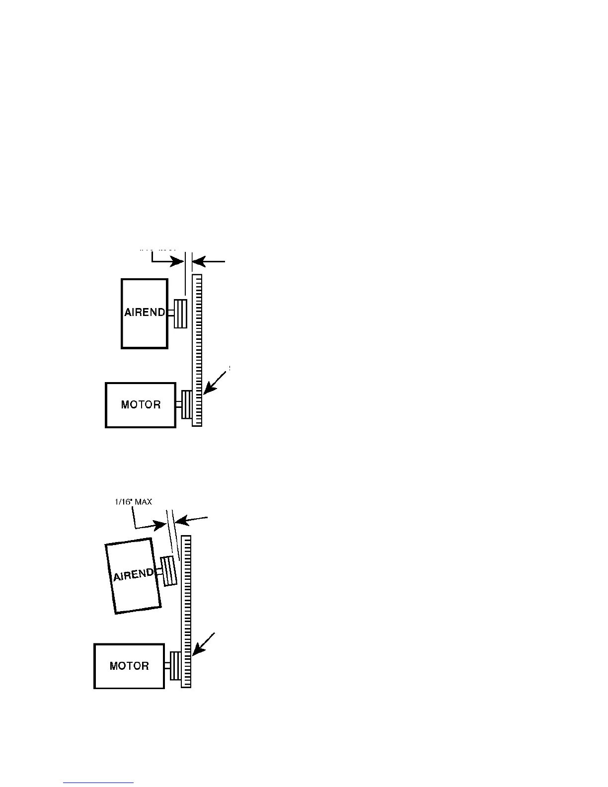
FIGURE 4.5-1 PARALLEL MISALIGNMENT
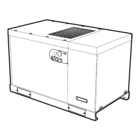
FIGURE 4.5-2 ANGULAR MISALIGNMENT
Align Sheaves
Ensure that the compressor is isolated from the
compressed air system by closing the isolation
valve and venting pressure from the drip leg.
Ensure that the main power disconnect switch is
locked and tagged.
An easy and effective method of checking alignment in
both directions between the driver and driven sheaves
utilizes an accurate straightedge.
Lay the straightedge across the face of the driver
(motor) sheave and check alignment of the driven
(airend) sheave.Then lay the straightedge across the
driven sheave and check that the driver sheave is
aligned.
Alignment should be within 1/16” (1.6 mm) maximum
when measuring the gap between the straightedge
and the rim of the opposite sheave in each direction.
This alignment is factory set and should only require
resetting if the drive motor or airend is removed.
The following steps should be taken to insure proper
alignment of all components.
1. Remove the cooler box top panel.
2. Holding the straightedge against the front of the
airend sheave, measure the amount of misalignment
seen on the motor sheave. If misalignment is less than
1/16” (1.6 mm) then reinstall cooler box panel prior to
operating unit.
3. If misalignment is more than 1/16” (1.6 mm), the
motor sheave bushing must be loosened for reposi-
tioning.
To reposition the motor sheave:
1. Remove drive belts (See Section 4.6).
2. Remove the three hex head screws that hold the
sheave to the sheave bushing. See Figure 4.5-3.
3. Lubricate the thread and end of screws that were
just removed.
4. Reinstall all three screws in the holes of the bushing
that are threaded.
5. Slowly tighten the three screws evenly until the
sheave is pressed from the bushing. (Light tapping on
bushing may assist removal.)
6. Remove the screws from the holes.
1/16” (1.6mm) MAX
1/16” (1.6mm) MAX
STRAIGHTEDGE
STRAIGHTEDGE
4.5 SHEAVE ALIGNMENT
Any degree of sheave misalignment will result in a
reduction of belt life. Misalignment of belt drive should
not exceed 1/16 in. (1.6 mm).
Parallel misalignment occurs when the drive and dri-
ven shafts are parallel, but the two sheaves lie in dif-
ferent planes (See Figure 4.5-1).
Angular misalignment occurs when the two shafts are
not parallel (See Figure 4.5-2).
 Loading...