18
Before beginning any work on the compressor, open,
lock and tag the main electrical disconnect and
close the isolation valve on the compressor dis-
charge.Wait 2 minutes after stopping to allow inter-
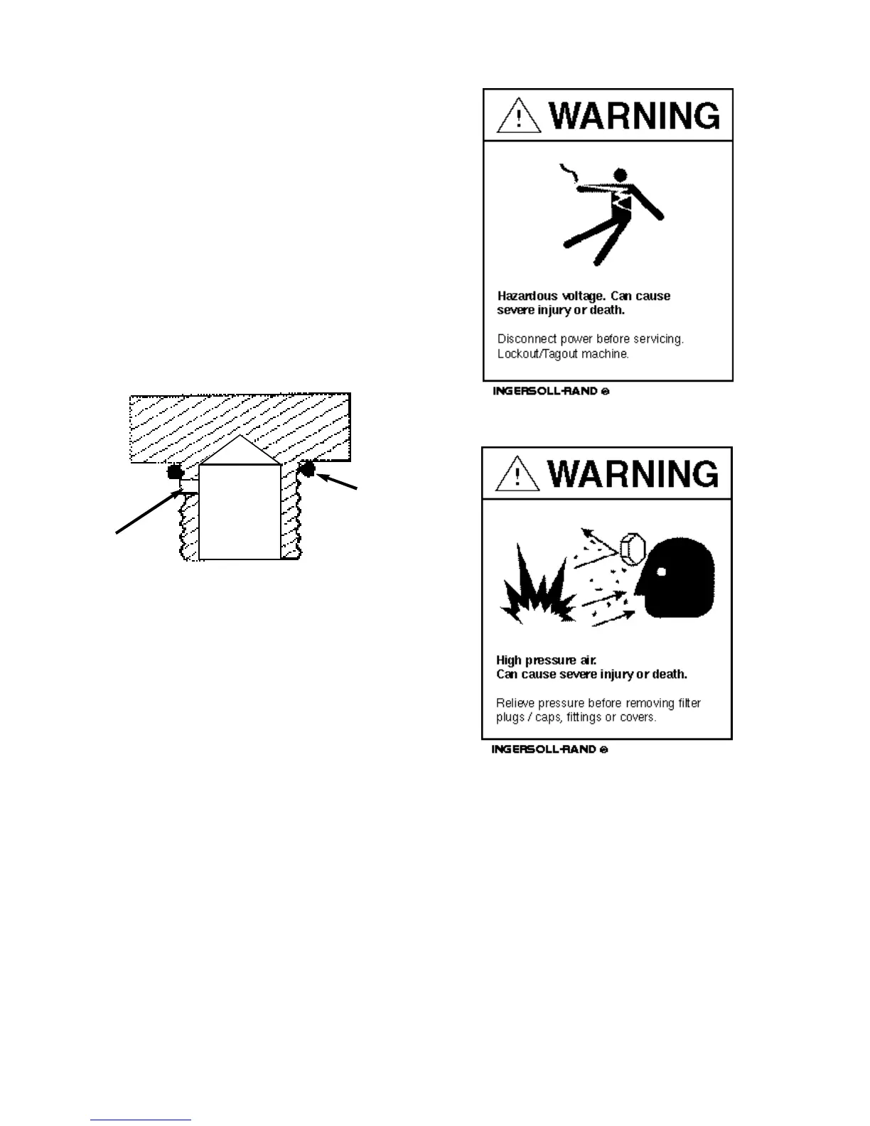
nal pressure to dissipate.Vent residual pressure
from the unit by slowly unscrewing the coolant fill
plug one turn. Unscrewing the fill plug opens a vent
hole, drilled in the plug, allowing the pressure to
release to atmosphere (See Figure
4.3-1). A slight mist or oil droplets may be visible
during venting. Do not remove fill plug until all pres-
sure has vented from the unit. Also vent piping by
slightly opening the drip leg valve.When opening
the drain valve or removing the coolant fill plug,
stand clear of the valve discharge, wear work gloves
and appropriate eye protection.
4.4 PRESSURE RELIEF VALVE CHECK
Under normal operating condition a “try lever test” must
be performed every month . Under severe service condi-
tions, or if corrosion and/or deposits are noticed within
the valve body, testing must be performed more often. A
“try lever test” must also be performed at the end of any
non-service period. CAUTION! High pressure air will
discharge through the discharge ports of the valve
during “try lever test”.Wear ample clothing, gloves,
safety glasses and ear protection during valve test-
ing. Run the compressor for about 10 minutes by vent-
ing air from the system to let the unit warm up.With the
unit running, test at or near maximum operating pressure
by holding the test lever fully open for at least 5 seconds
to flush the valve seat free of debris.Then release lever
and permit the valve to snap shut. If lift lever does not
activate, or there is no evidence of discharge, discontin-
ue use of equipment immediately and contact a licensed
contractor or qualified service personnel.
FIGURE 4.3-1 COOLANT FILL PLUG WITH
VENT HOLE
VENT
HOLE
O-RING
 Loading...