2 Wiring
- 6 -
2�2 Terminals
■
Terminals of Main Circuit
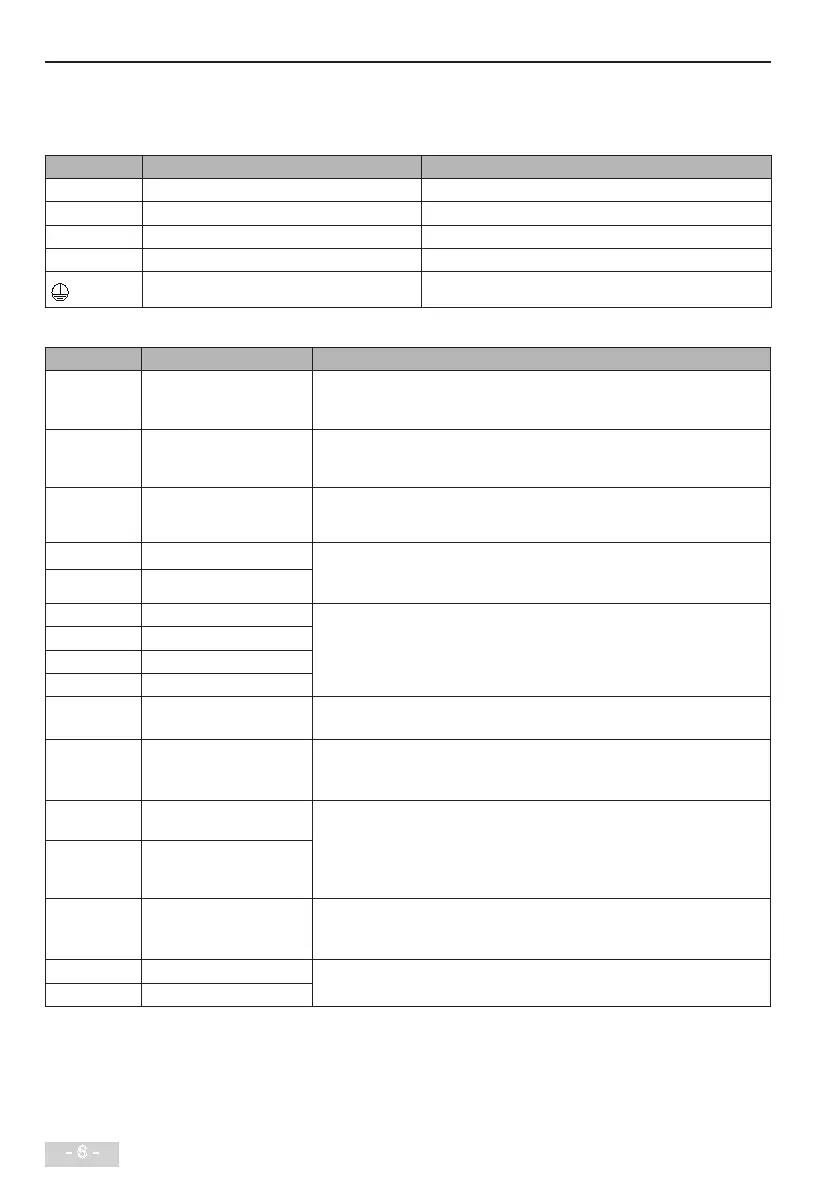
Table 2-1: Main circuit terminals of three-phase
Terminal Terminal Name Description
R, S, T Three-phase power supply input terminals Connect to the three-phase AC power supply�
P(+), (-) Positive and negative terminals of DC bus Common DC bus input point�
P(+), BR Connecting terminals of braking resistor Connect to a braking resistor�
U, V, W Output terminals Connect to a three-phase motor�
Grounding terminal Must be grounded�
■
Terminals of Control Circuit
Terminal Terminal Name Description
+10V-GND +10 VDC power supply Provide +10 VDC power supply externally� Usually, it provides power supply to the
external potentiometer with resistance range of 1 to 5 kΩ.
Max� output current: 10 mA�
+24V-COM +24 VDC power supply Provide +24 VDC power supply externally� Usually, it provides power supply to DI/
DO terminals and external sensors�
Max� output current: 200 mA�
OP Input terminal of external
power supply
Connect to +24 VDC by default� Whether it connects to +24 V or COM is decided by
jumper J7� When DI1 to DI5 need to be driven by the external signal, OP needs to
be connected to the external power supply and be disconnected from +24 VDC�
AI1-GND Analog input 1 AI1 input voltage range: 0 to 10 VDC�
AI2 input range: 0 to 10 VDC or 4 to 20 mA�
Impedance: 22 kΩ.
AI2-GND Analog input 2
DI1-COM Digital input 1 Optical coupling isolation, compatible with dual-polarity input�
Impedance: 2.4 kΩ.
Input voltage range: 9 to 30 VDC�
DI2-COM Digital input 2
DI3-COM Digital input 3
DI4-COM Digital input 4
DI5-COM High-speed pulse input Besides features of DI1 to DI4, it can be used for high-speed pulse input�
Max� input frequency: 20 kHz�
AO1-GND Analog output 1 Voltage or current output, determined by jumper J5 on the control board�
Output voltage range: 0 to 10 VDC�
Output current range: 0 to 20 mA�
DO1-CME Digital output 1 Multi-function open-collector output�
Voltage range: 0 to 24 VDC�
Current range: 0 to 50 mA�
Output pulse frequency range: 0 to 50 kHz�
For jumper J6, CME and COM are shorted by default�
FM-COM High-speed pulse output
485+-485- Communication terminal Modbus protocol (baud rate: 300 to 115200 bps)
Max� nodes: 32�
Terminal resistance switch: S1�
T/A-T/B Normally closed terminal Contact driving capacity: 250 VAC, 0�2 A; 30 VDC, 1 A�
T/A-T/C Normally open terminal
 Loading...
