Connector / Header Locations and Pin-outs Intel
®
Server Board S5500BC TPS
Intel order number: E42249-003 Revision 1.0
58
5.6.3 Serial Port Connectors
The Intel
®
Server Board S5500BC provides one external 9-pin Serial ‘A’ port (J8A1) and one
internal 9-pin Serial B port header (J9A1). Serial A is a standard DB-9 interface for pedestal
products and RJ-45 for rack products and is located on the rear I/O panel of the server board.
The following tables define the pin-outs for each:
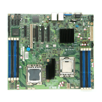
Table 19. 9-pin External Serial A Port Header Pin-out (J8A1)
Pin Signal Name Description
1 SPA_DCD
2 SPA_SIN_N
3 SPA_SOUT_N
4 SPA_DTR
5 GND
6 SPA_DSR
7 SPA_RTS
8 SPA_CTS
9 SPA_RI
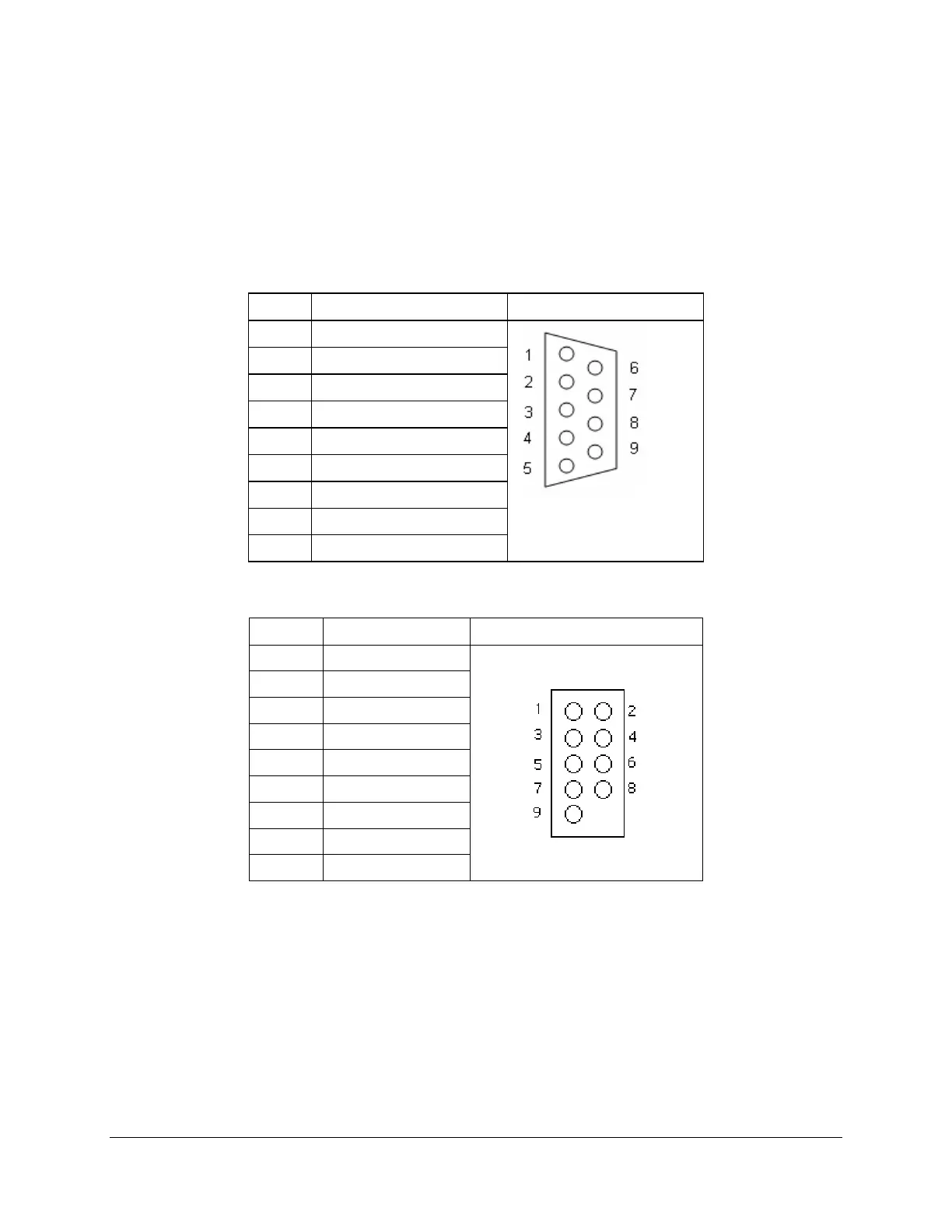
Table 20. Internal Serial B Port Header Pin-out (J9A1)
Pin Signal Name Serial Port A Header Pin-out
1 DCD
2 DSR
3 RXD
4 RTS
5 TXD
6 CTS
7 DTR
8 RI
9 GND
5.6.4 USB and GigE Connector
The Intel
®
ICH10R I/O Controller Hub on the Intel
®
Server Board S5500BC supports eleven
USB ports. Four ports are connected to two USB+RJ-45 NIC stacked connectors on the rear
panel of the server board. The following table lists the pin-out information for the external USB
connectors (J5A1, J6A1).
 Loading...


