Goodrive20 inverters Installation guidelines
18
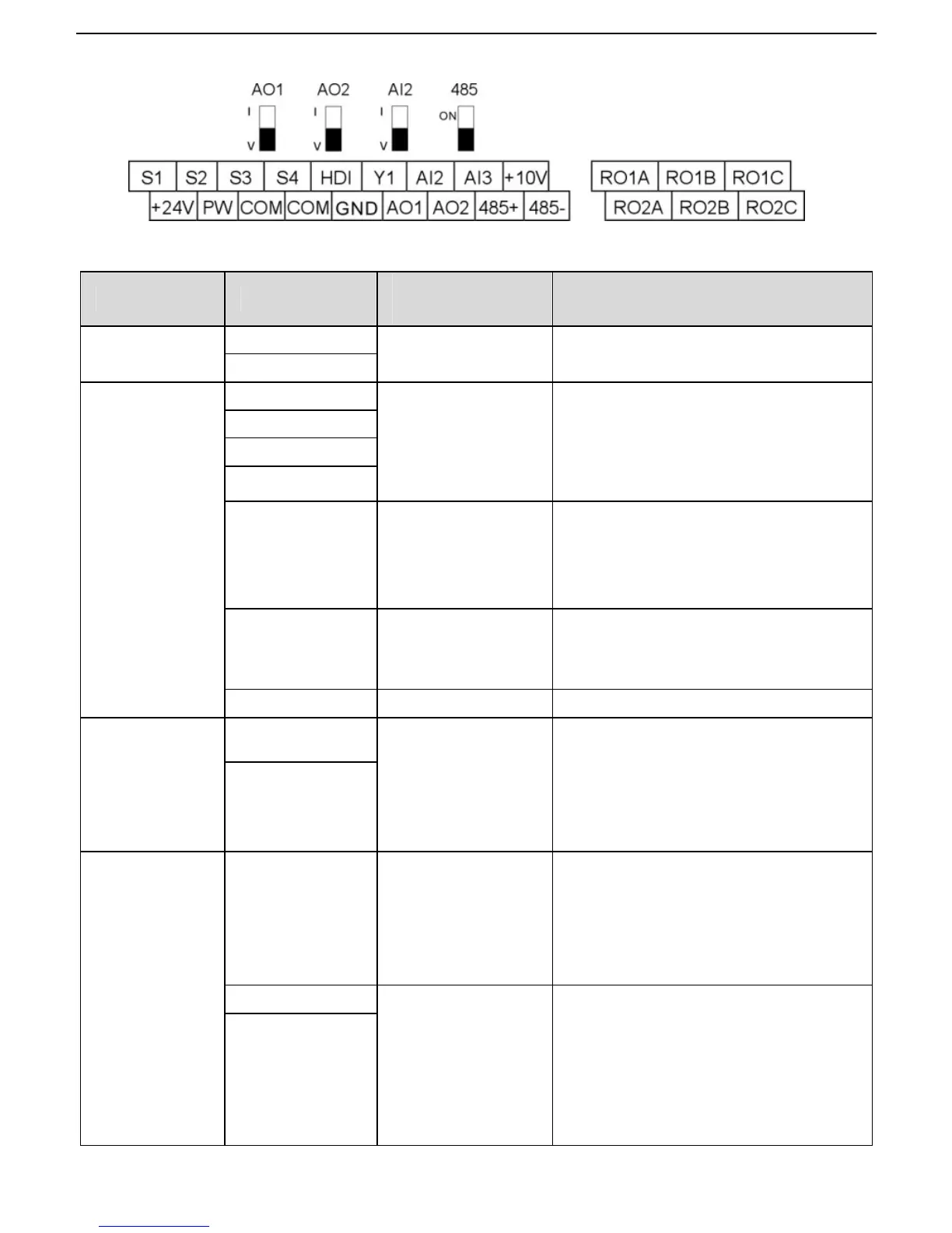
3.2.5 Terminals of control circuit
Figure 3-10 Terminals of control circuit
Type Terminal name
Function
description
Technical specifications
Communication
485+
485 communication
485 communication interface
485-
Digital
input/output
S1
Digital input
1. Internal impedance:3.3kΩ
2. 12~30V voltage input is available
3. The terminal is the dual-direction
input terminal
4. Max. input frequency:1kHz
S2
S3
S4
HDI
High frequency
input channel
Except for S1~S4, this terminal can be
used as high frequency input channel.
Max. inputfrequency:50kHz
Duty cycle:30%~70%
PW Digital power supply
To provide the external digital power
supply
Voltage range: 12~30V
Y1 Digital output Contact capacity: 50mA/30V
24V power
supply
+24V
24V power supply
External 24V±10% power supply and
the maximum output current is 200mA。
Generally used ad the operation
powersupply of digital input and output
or external sensor power supply
COM
Analog
input/output
+10V
External 10V
reference power
supply
10V reference power supply
Max. output current: 50mA
As the adjusting power supply of the
external potentiometer
Potentiometer resistance: 5kΩ above
AI2
Analog input
1. Input range: AI2 voltage and current
can be chose: 0~10V/0~20mA;
AI3:-10V~+10V.
2. Input impedance:voltage input:
20kΩ; current input: 500Ω.
3.Voltage or current input can be
AI3
 Loading...