20
Figure 3-12 NPN modes
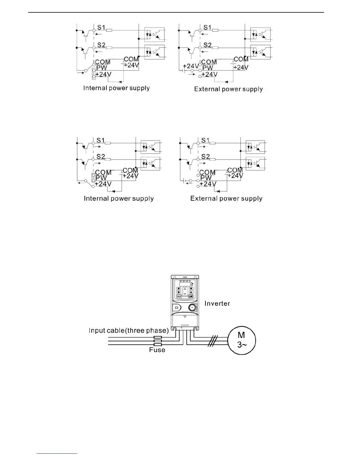
If the signal is from PNP transistor, please set the U-shaped contact tag as below according to the used
power supply.
Figure 3-13 PNP modes
3.3 Layout protection
3.3.1 Protecting the inverter and input power cable in short-circuit situations
Protect the inverter and input power cable in short circuit situations and against thermal overload.
Arrange the protection according to the following guidelines.
Figure 3-14 Fuse configuration
Note: Select the fuse as the manual indicated. The fuse will protect the input power cable from damage in
short-circuit situations. It will protect the surrounding devices when the internal of the inverter is short
circuited.
3.3.2 Protecting the motor and motor cables
The inverter protects the motor and motor cable in a short-circuit situation when the motor cable is
dimensioned according to the rated current of the inverter. No additional protection devices are needed.
 Loading...