Operation and Application
Copyright ©ITECH Electronic Co., Ltd. 46
⚫ Current AC: Constant current value and current slope
⚫ Current DC: Idc setting value and Idc slope, Realize the function of AC+DC,
DC offset setting range is 10% of the rating.
⚫ Parallel Resistance: Constant resistance value
⚫ Waveform (phase shift range: -90.0~90.0): select the waveform. Under CC
mode, and Unit PF is off, Waveform can be select.
Crest Factor: CF range is 1.414~5, and the range is limited by peak value.
Phase shift: Phase shift of voltage and current. Phase shift range within -
90°~90°. If programmed is positive it will be a leading power factor. If
programmed is negative it will be a lagging power factor.
Programming the load value (CC+CR)
The user can press [Set] and set the input resistance value in the main interface
of CS mode. Directly set the present value through the knob or press numeric
keys to input the value. In case of wrong input by numeric keys, press
to delete the present input.
5.3.5 Circuit Emulation (CE)
The electronic load simulates some real power environment of the DUT by
setting RLC and other parameters. In the circuit simulation mode, the circuit
topology can also be selected. Different topologies, different parameters are set
and different simulation states are achieved.
Press [Config] and enter to the configuration menu. Select constant mode to
CE.
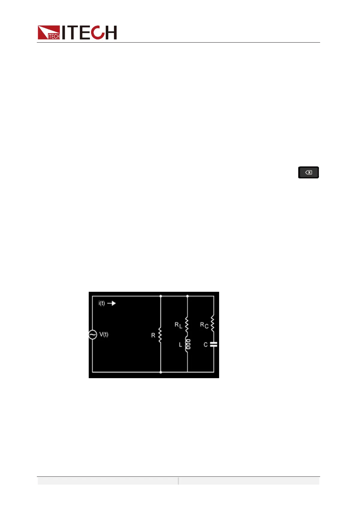
Parallel RLC Mode:
In this mode, the R L C parallel state is simulated and the circuit schematic is
shown in the figure below.
Rectifier single phase RLC
This mode simulates a single-phase rectifier R L C circuit, and the circuit
schematic is shown in the figure below.
 Loading...