Home
ITech
Measuring Instruments
IT8200 Series
ITech IT8200 Series User Manual
4
of 1
of 1 rating
147 pages
Give review
Manual
Specs
To Next Page
To Next Page
To Previous Page
To Previous Page
Loading...
Sys
tem-Re
lated Functions
Copyright ©ITECH Electr
onic Co., L
td.
60
Chapter6
System-Rel
ated Functions
6
.1
System Menu Reference
Press
[
Shift]
+
(System
)
to
enter
the
menu
f
unction
.
At
this
time,
LCD
displays
optional
menus.
Select
and
edit
the
m
enu
items
by
pressing
the
Up,
Down, Left and Ri
ght keys. Speci
fic menu items
are shown bel
ow
.
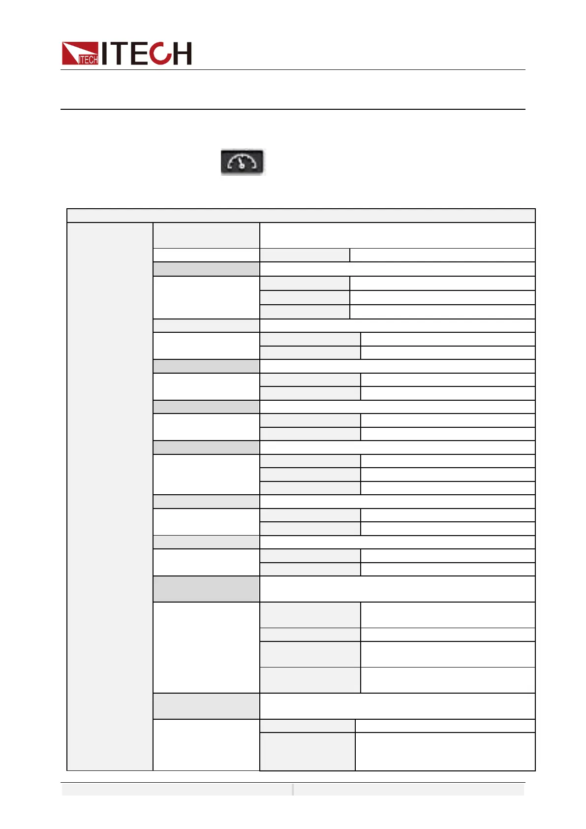
System
Source
Device operation
mode
Set the instrument
mode
Load
Load mode
Phase mode
Set the
AC input mode
1-Phase
Single phase
3-Phase
Three phase
Reverse
Reverse phase
Couple mode
Set input mode
AC
AC mode
DC
DC mode
Load C phase loss
C phase disabled
mode
Disable
Disable this functi
on
Enable
Enable this function
Rectified
Rectified function swi
tch
On
Enable rectified
mode
Off
Disable rectified
mode
Integrity
Integrity mode
Full
Full waveform
Pasitive
Positive half wave
form
Negative
Negative half wave
form
OFF mode
Set the input turn o
ff mode
Open-Z
Open circuit mode
High-Z
High impedance
mode
Regulation speed
Regulation speed o
f load
Fast
Fast speed
Slow
Slow speed
External
Synchronization
External Synchroni
zation
On/Of
f
Enable/disabl
e
External
Synchronization func
tion
Phase delay
External input phase
delay
BA
Phase delay for
BA(only for three
phase mode)
CA
Phase delay for
CA(only for three
phase mode)
External
programme
External analog func
tion:
Status
Set the ON/OFF s
tate
Mode
AM:
Adjust the ampl
itude
Amplifier
:
R
eal
-
time input
and
power
Amplifier
.
61
63
Table of Contents
default chapter
3
Limitation of Warranty
3
Safety Symbols
3
Warranty
3
Environmental Conditions
5
Regulatory Markings
5
Waste Electrical and Electronic Equipment ( WEEE) Directive
6
Compliance Information
7
Table of Contents
8
Chapter1 Overview
11
Brief Introduction
11
Models and Options
12
Optional Accessories
13
Instrument Size Introduction
13
Chapter2 Instrument Introduction
19
Unpacking and Transportation
19
Verifying the Shipment
20
Front Panel
21
Keyboard
21
Push-On Knob
23
Rear Panel
23
Chapter3 Installation
25
Connectiong the Power Cord
25
Connecting Test Lines ( Optional)
28
Installing Fiber Cables (Only for IT8230-350-180)
32
Chapter4 Getting Started
34
Power-On the Instrument
34
Home-Screen Overview
35
Set Load Parameters
38
Input On/Off Control
39
Chapter5 Operation And Application
40
Select Phase
40
Select the Input Mode
40
AC Input Mode
41
DC Input Mode
41
AC Load Function
41
Constant Current Mode (CC)
41
Constant Resistance Mode (CR)
43
Constant Power Mode (CP)
44
Constant Apparent Power Mode (CS)
45
Constant Current +Constant Resistance (CC+CR)
47
Circuit Emulation (CE)
48
DC Load Function
49
Constant Current Mode (CC)
50
Constant Resistance Mode (CR)
50
Constant Voltage Mode (CV)
50
Constant Power Mode (CP)
50
Complex Operation Mode
51
Rectified Mode
53
Waveform Selection
56
C Phase Loss
57
Three-Phase Unbalance Simulation
57
Load Angle and Unload Angle Control
57
Sweep Function
58
Synchronization Function
60
Chapter6 System-Related Functions
62
System Menu Reference
62
Menu Function
66
Set the Communication Interface
68
View the System Information
68
Configuration Menu Reference
68
Key Lock Function
69
Switching Local/Remote Mode
69
Save and Recall Operations
69
Protection Function
70
Out-Of-Range Frequency Protection
71
Undervoltage Protection
71
Peak over Voltage Protection
71
Rms Ocp
72
Peak over Current Protection
72
Over-Power Protection (OPP)
73
Over-Temperature Protection (OTP)
73
Screen Capture Function
73
Trigger Function
73
Query the System Log
74
Query the Energy
74
Set Parallel Operation Mode
74
Remote Measurement Function
77
Digital I/O Function
77
Analogue Function (Ext-Program) (Optional)
80
Chapter7 Measurement Functions
84
Meter Mode
84
Oscilloscope Mode
85
Harmonic Measurement
87
Recorder Function
89
Chapter8 Configuration Arbitrary Waveform
90
List Function
90
Create a New List File
90
Select/Run List File
92
Import/Export List File
93
Setting of Surge/Sag Configuration
93
Self-Defined Waveform Function
95
Thd
95
Selfdefined
97
Chapter9 Technical Specifications
99
Main Technical Parameters
99
It8203-350-30U
99
It8205-350-30U
101
It8206-350-90
103
It8209-350-90
105
It8212-350-90
108
It8215-350-90
110
It8230-350-180
112
It8245-350-270
115
It8260-350-360
117
It8275-350-450
119
It8290-350-540
122
It82105-350-630
124
It82120-350-720
126
It82135-350-810
130
It82150-350-900
132
It82165-350-990
135
Supplemental Characteristics
137
Chapter10 Remote Control
138
USB Interface
138
LAN Interface
138
CAN Interface
141
GPIB Interface (Optional)
142
Interface (Optional)
143
Commonly Used Commands Overview
144
Demo Software Introduction
145
Appendix
146
Specifications of Red and Black Test Lines
146
Other manuals for ITech IT8200 Series
Programming Guide
137 pages
4
Based on 1 rating
Ask a question
Give review
Questions and Answers:
Need help?
Do you have a question about the ITech IT8200 Series and is the answer not in the manual?
Ask a question
ITech IT8200 Series Specifications
General
Brand
ITech
Model
IT8200 Series
Category
Measuring Instruments
Language
English
 Loading...