Function and Features
Copyright © ITECH Electronic Co., Ltd. 35
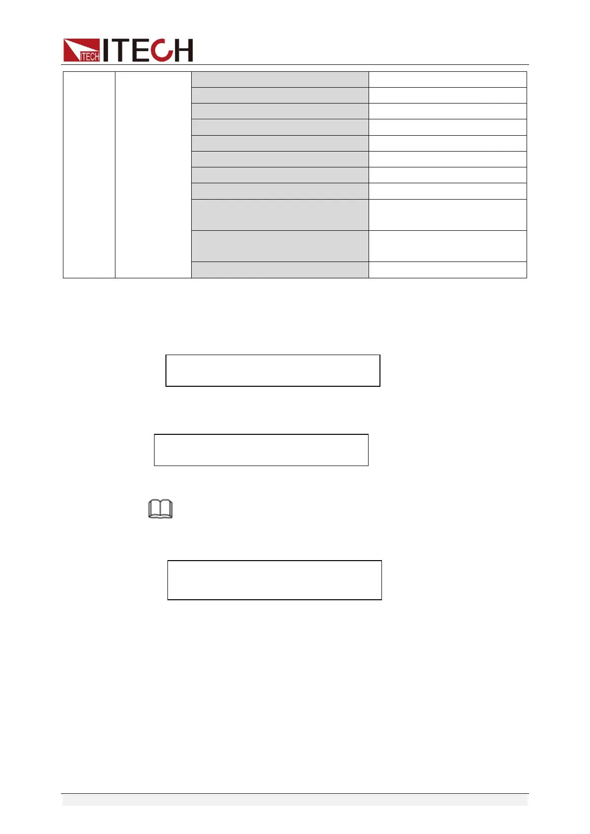
1:Voltage on level=0.000V Set Von voltage value
2:Voltage on Delay=0.00S Set Von voltage delay time
3:Current Range=0.000A Set working current range
4:Start Power=0.000W Set initial power value
5:Step Power=0.000W Set step power value
6:Step Delay=0.00S Set step delay time
7:End Power=0.000W Set cutoff power value
8:OPP Voltage=0.000V Set OPP value
9:Max Trip Power =0.000W Set overpower range (maximum
value)
10:Min Trip Power =0.000W Set overpower range (minimum
value)
Save OPP File=1 (1-5) Save OPP test documents
Operating steps:
1. Press [Trig] key to start OPP test. If within range, PASS the test and the
board will display as follows:
9.996V 0.0007A
0.01W 49.10W PASS STOP
If not, there is FAULT and the board will display as follows:
9.996V 0.0007A
0.01W 48.6W FAULT STOP
2. End test. The User should return back to setting screen for resetting.
NOTE
If the set OPP voltage value is higher than the power voltage value, the OPP will fail to
operate and the board will display as follows:
9.996V 0.0007A
0.01W 0.1W FAULT STOP
3.12 Battery discharge test function
In the IT8800 series electronic load, constant current mode is applied for
capacity test with programmatic setting of cutoff level/capacity/discharging time
If cutoff level is set as the stop condition, the system determines whether the
battery is about to reach the set threshold value or unsafe status when the
battery voltage is low, and if yes, an automatic stop will be activated. During the
test, the voltage, time and discharged capacity of the battery can be observed.
Battery discharge test is a necessary step before battery replacement for it can
reflect reliability and remaining life of battery.

 Loading...


