Function and Features
Copyright © ITECH Electronic Co., Ltd. 47
3.19.5 Voltage fault indication terminal
When load is under overvoltage protection or terminal reverse polarity
protection, VF pin voltage fault indication terminal outputs high level.
3.19.6 Current monitoring (I Monitor)
The 0-10V analog quantity output signal of current monitoring output terminal
represents input current to which the terminal belongs from 0 to full range. An
external voltmeter or oscilloscope can be connected to display input current
change.
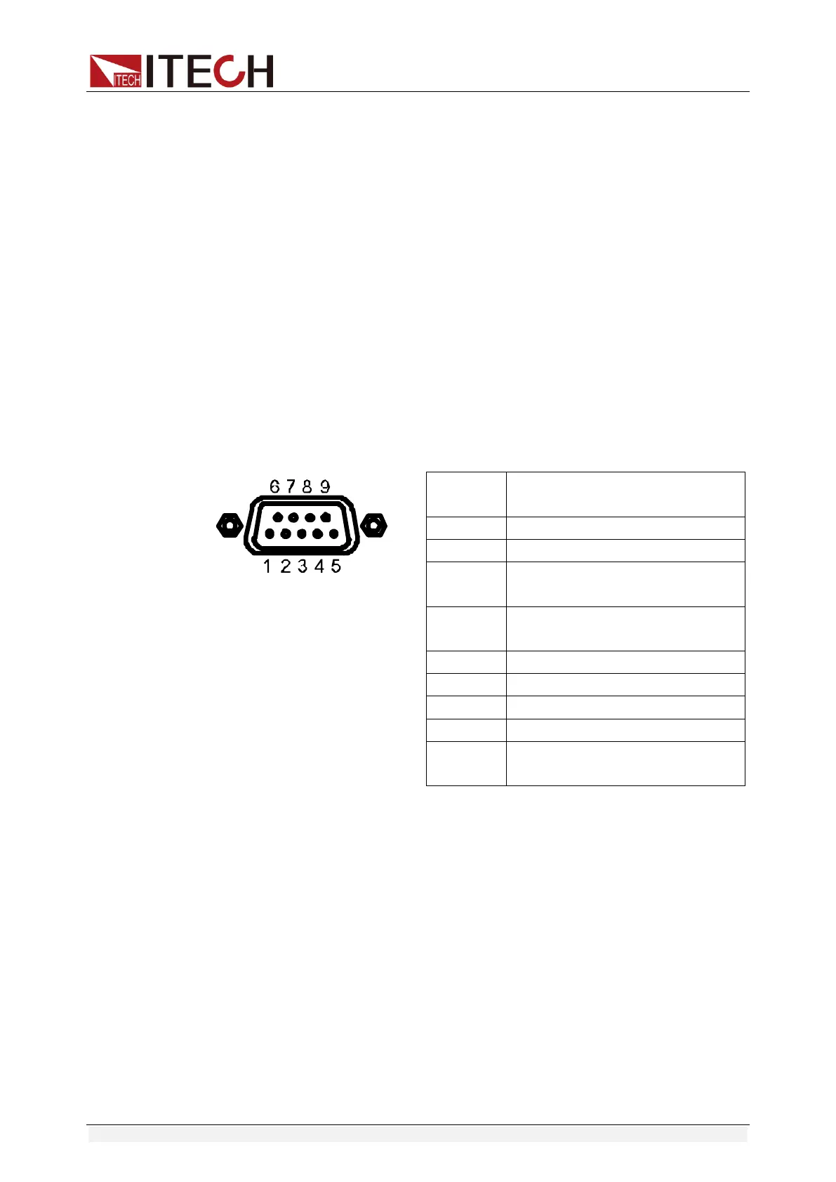
3.20 External Signal Control Interface
Besides the RS232 communication interface, the rear panel is also equipped
with a DB-9 COM interface, which is the external signal control interface used in
auto test. The pin definitions are as follows.
Pins of Plug
number
Description
1
The auto test runs last step.
2
The auto test starts to run.
3
During the auto test, the input is
turned on.
4
Output the failure signal of the auto
test.
5
GND
6
The auto test runs next step.
7
The auto test pauses.
8
The auto test outputs via signal.
9 The warning tone signal of auto test
outputs.
You can control the auto test process and test results by transmitting
input/output signals through external signal control interface. Different pins of
the interface control different functions. Detailed instructions are listed on the
above table.
Under external analog quantity control mode, you can switch CC mode through
pin 1 of the interface and switch CV mode through pin 6.
3.21 Auto test function
The IT8800 series electronic load delivers strong auto test functions, which can
analog several tests. A total of 10 groups of test files can be edited, and each
group test file has 10 steps. Therefore, a maximum of 100 steps can be edited
and saved in EEPROM (address).
Edit test files following the steps below:

 Loading...


