Function and Features
Copyright © ITECH Electronic Co., Ltd. 38
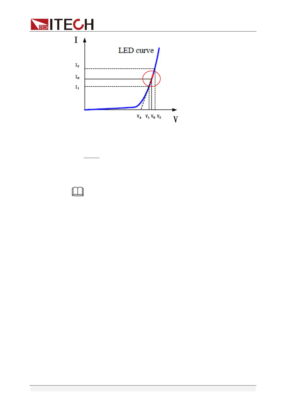
According to four parameters above and the V-I curve of LED, you can
calculate the value of R and Vd.
NOTE
The value of V2, V1, I2 and I1 should be close to the static working point of LED as
shown in the red circle above.
Or you can roughly calculate the value of R and Vd with the following equation.
V
d
=V*0.8 R=0.2V/I
Where:
V: constant working voltage of load LED of LED constant current source;
I: output current of LED constant current source;
V
d
: break-over voltage of diode (string);
R: constant resistance.
In the example: Vd=50V*0.8=40V R=(0.2*50V)/0.2A=50Ω.
3.14 Measurement of voltage rise time
The IT8800 series electronic load is provided with special voltage rise/drop time
measurement function. This function gives a simple analog of voltage rise/drop
speed of oscilloscope test power.
Operation methods:
Set initial voltage and final voltage
1. Press [Shift] + 6 keys to enter configuration menu. Press Right key. Select
“Measure” and press [Enter] key.
2. Press Left/Right Key to select “TimeV1”. Press [Enter] key. Press numeric
keys to set initial voltage value and press [Enter] key.
3. Press Left/Right Key to select “TimeV2”. Press [Enter] key. Press numeric

 Loading...


