ELECTRICAL SYSTEM 8
en-85
8Electrical System
8.1 GENERAL INFORMATION
General precautions to decrease electrical problems are -
• Make sure that all the connections are clean and correctly fastened.
• Check the interlock system and fuses at normal intervals. If the interlock system does not operate correctly
and you can not correct the problem, contact an authorized Jacobsen Dealer.
• Keep the wiring harness away from hot surfaces and moving parts.
• Make sure the engine, seat and armrest wire harnesses are securely connected to the mower wire harness.
• Check the battery and the alternator.
• Do not wash or pressure spray around electrical connections and components.
The electrical system is monitored and controlled by the Engine Control Unit (ECU), Mower Control Units (MCU) and
the visual display. There are CAN diagnostic connectors located under the armrest control panel and under the hood
on the left side of the engine. A four pin Kubota Diagmaster connector is located on the left side of the engine.
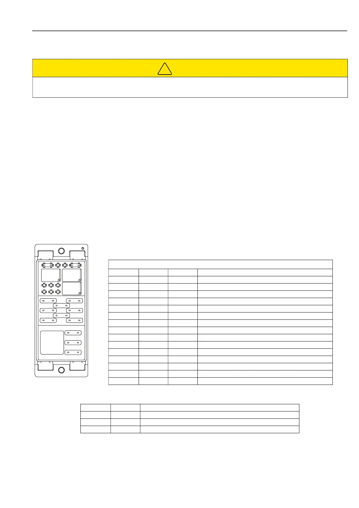
There are fifteen fuses and four relays that are used to protect the mower circuits. The mini/ATO fuses and relays are
located under the mower hood, on the left side of the engine. The 60A maxi fuse is found in the positive battery cable
near the alternator.
8.2 FUSE AND RELAY/COMPONENT IDENTIFICATION ______________________________
FUSES
Relays
CAUTION
Always turn the ignition switch to the off position and disconnect the negative (BLACK) battery cable before you
inspect or service the electrical system.
FUSE IDENTIFICATION
Fuse Type Rating Protected Circuits
F1 ATO 10A ECU Power
F2 ATO 25A Main Relay Load Circuit
F3 ATO 5A Start Signal
F4 Mini 5A EGR
F5 ATO 15A Premium Seat Compressor / Armrest
F6 ATO 20A MCU Power
F7 ATO 25A MCU Relay Power
F8 ATO 20A MCU CPU Power
F9 ATO 40A Glow Plug Relay
F10* ATO 20A Start Relay
F11 ATO 20A Work Lights
F12 Mini 5A T4F Main Relay Coil
F13 Mini 5A Not Used
F14 ATO 10A 12V Accessory Outlet
F15 Maxi 60A Alternator Output (Located in Positive Battery Cable)
Relay Rating Circuits
K1 Micro Main Relay
K2 40A Glow Plug Relay
K3 Micro Start Relay
!
K3 K1
K4
F4
F13
F12
K2
F8
F5
F3
F10
F11
F14
F6
F1
F9
F2
F7
 Loading...