3.2 Rear connecƟons
3.2 Rear connecons
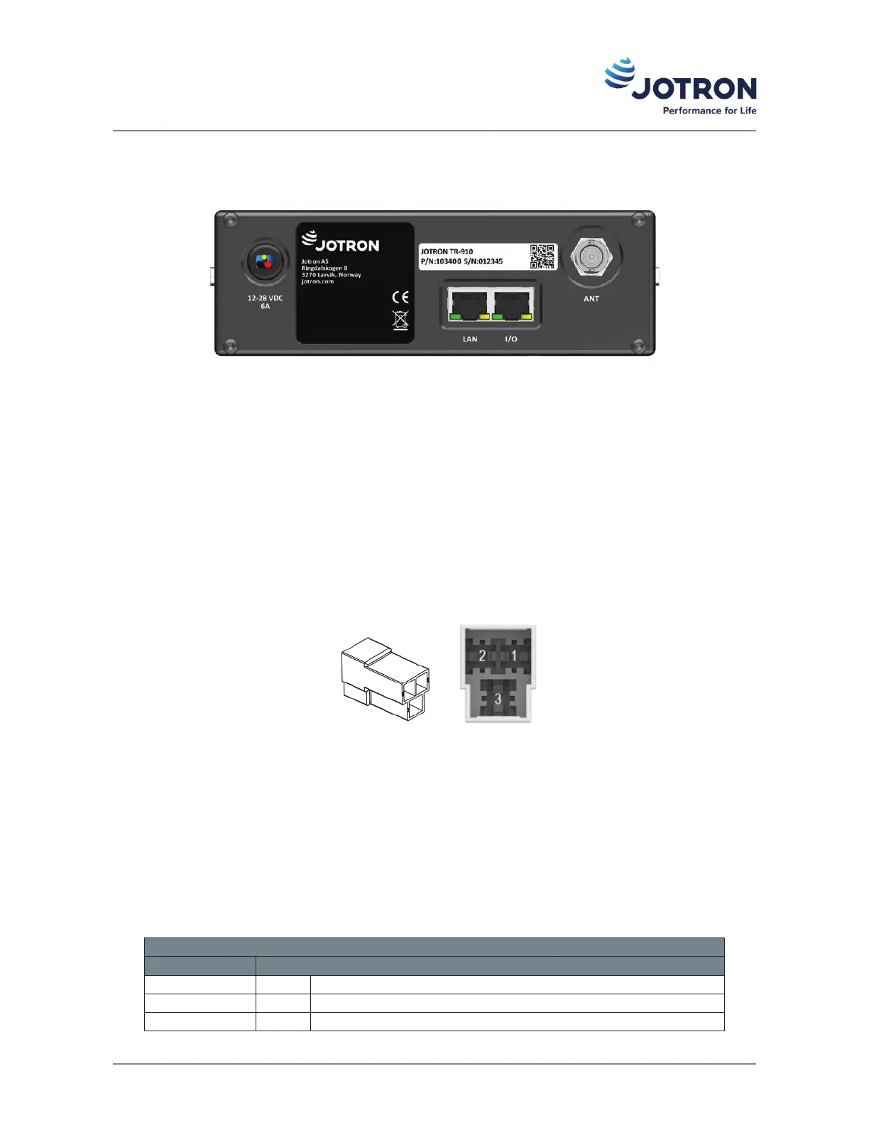
Figure 4: Rear view of TR-910
3.2.1 Antenna connector (50 Ω BNC)
The antenna connector is of BNC type and shall be connected to an antenna with 50 Ω impedance suited for
use in the operang frequency band, either connected directly or via a lightning arrestor. The arrestor is to
protect the transceiver from lightning strikes. If other types of connectors are required adapters are readily
available for N and TNC type connecons.
3.2.2 DC input connector
The DC connector is of a rugged FF 250 quick connect type for easy connecon in vehicles.
Figure 5: DC-connector
The Red wire is the posive connecon and the Black wire is the negave connecon (GND). When installed in
a vehicle, the Green/Yellow wire is for connecon to the ignion key voltage. When connected to the vehicle
ignion, the radio will automacally turn on/off with the ignion key. For other types of installaons this wire
should be connected to the posive supply. The radio operates from a DC supply of +12 V to +28 V +/-10%.
Table 17: DC connector, pin out
DC input connector
Name Pin Funcon
Red 1 Connected to + DC voltage
Black 2 Connected to ground
Green/Yellow 3 Ignion key + DC voltage sense
Doc. No.: 103614 TR-910 Operator Rev. AB jotron.com 23
 Loading...