❻
❺
❼
❹
❸
D
E
❶
❷
A
B
C
Turn thread trimming cam
❸
in the direction of
arrow until the outer periphery of thread trimming
cam groove
C
comes in contact with roller
❷
and
stops. At this position, x thread trimming cam
setscrew
❼
.
Illustration as observed from
D
(right side face)
❷
C
❸
❹
❷
C
Correct (
F
)
❷
C
Wrong (
G
)
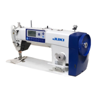
5-3. Adjusting the thread trimmer
5-3-1. For checking of the thread trimming
cam timing
The purpose of the adjustment of the thread trim-
ming is to bring marker line
A
on electrical box
cover
❺
to the portion between the colorless marker
dots
B
and
C
on handwheel
❻
.
1) Tilt the sewing machine head.
2) Turn handwheel
❻
by hand in the normal direc-
tion of rotation until the thread take-up lever goes
up slightly below the upper dead point. Press cam
follower
❶
with ngers to the left (in direction of
arrow
E
) to t roller
❷
to in groove
C
in thread
trimming cam
❸
.
3) In this state, turn handwheel
❻
in the direc-
tion which is opposite to the normal direction of
rotation until handwheel
❻
will go no further. (If
the handwheel is turned further, it reaches the
position at which cam follower
❶
starts moving.)
At this time, adjust so that the marker line
A
on
electrical box cover
❺
is brought to the portion
between the colorless marker dots
B
and
C
on
handwheel
❻
.
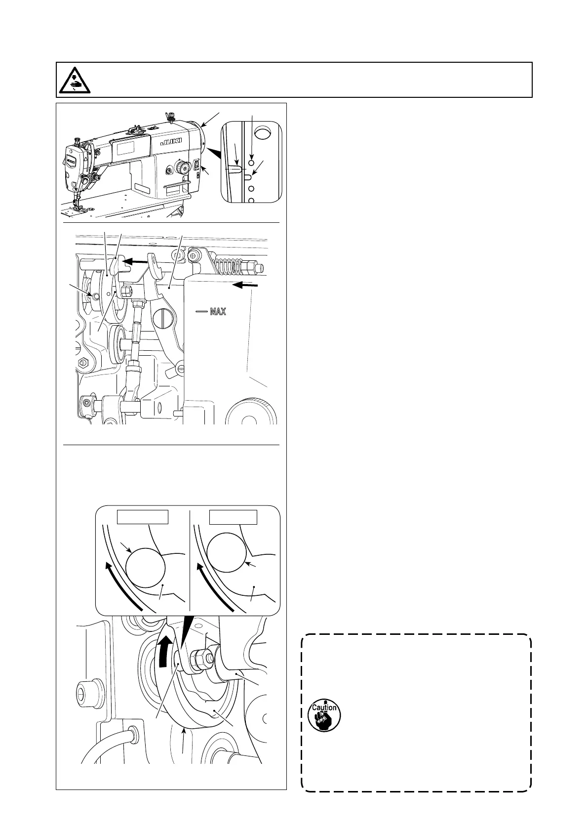
5-3-2. Adjustment of the thread trimming
cam timing
1) Tilt the sewing machine head.
2) Loosen the screws No.1 and No. 2 of thread trim-
ming cam setscrew
❼
in the written order.
3) Align marker line
A
on electrical box cover
❺
with the colorless marker dot
B
on handwheel
❻
.
4) Pressing cam follower
❶
to the left (in the direc-
tion of arrow
E
), engage thread trimming cam
❸
with roller
❷
. Then, turn only thread trimming
cam
❸
with ngers in the direction which is op-
posite to the normal direction of rotation of feed
driving shaft
❹
until it will go no further without
turning feed driving shaft
❹
. At this position,
tighten the screws No. 1 and No. 2 of thread trim-
ming cam setscrew
❼
in the written order while
pressing thread trimming cam
❸
against roller
❷
.
The alignment point between thread
trimming cam
❸
and roller
❷
is position
(
F
) from which cam follower
❶
starts
moving. Position (
G
) at which you feel
that thread trimming cam
❸
comes in
contact with roller
❷
for the rst time
during adjustment is not the correct
alignment position.
*
Be sure to correct the thread trimming
cam timing carefully since it largely
aects the loop spreading timing.
WARNING :
Turn OFF the power before starting the work so as to prevent accidents caused by abrupt start of the
sewing machine.
– 56 –
 Loading...