EasyManuals Logo
Home>JUKI>Sewing Machine>HZL-NX7

JUKI HZL-NX7 Service Manual

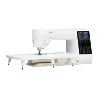
JUKI HZL-NX7
40 pages
To Next Page IconTo Next Page
To Previous Page IconTo Previous Page
Page #12 background imageLoading...
Page #12 background image
– 10 –
[5] PCB connection diagram
• Main PCB
Connec-
tor No.
Destination
Termi-
nal No.
CN13 Presser-lifter
STM
1
A
4.0Ω
2 A
3 B
4.0Ω
4
B
CN14 Top feed STM 1
A
4.0Ω
2 A
3 B
4.0Ω
4
B
CN15 Thread tension
STM
1
A
4.0Ω
2 A
3 B
4.0Ω
4
B
5 GND
6 Origin detection signal
7 5V
CN16 BH sensor 1 GND
2 BHR SW
3 BHS SW
4 3.3V
CN17 SW/slide vol-
ume PCB
1 LED G
2 LED R
3 Reverse stitch switch
4 S/S switch
5 Thread trimming switch
6 Needle up/down switch
7 Auto-lifter switch
8 Lock stitch switch
9 GND
10 Speedcontrolvariable
resistor
11 GND
12 3.3V
CN18 Reserve
(Unused)
2 GND
4 GND
CN19 PanelI/Fcable
asm.
1 5V
2 5V
3 GND
4 GND
5 RXD
6 TXD
7 S.STATE
8 UDET
9 Reset
10 5V
11 5V
12 Panel detection signal
13 GND
14 GND
15 NC
CN17
CN6
CN31
CN3
CN15
CN13
CN20
CN5
CN14
CN4
CN29
CN25
CN30
CN9
CN19
CN27
CN28
CN26
CN16
CN2
CN18
CN34
CN1
Connec-
tor No.
Destination
Termi-
nal No.
CN1 Debug
(Unused)
1 3.3V
6 GND
CN2 Flash memory
interface
1 5V
5 GND
CN3 Needle throwing
STM
1
A
5.0Ω
2 A
3 B
5.0Ω
4
B
CN4 Feed STM 1
A
4.0Ω
2 A
3 B
4.0Ω
4
B
CN5 Thread trimming
STM
1
A
4.0Ω
2 A
3 B
4.0Ω
4
B
5 GND
6 Origin detection signal
CN6 Potentiometer
cableasm.
1 3.3V
2 Position detection
signal
3 GND
CN9 Throat plate
switch PCB
1 Throat plate switch 1
2 Throat plate switch 2
3 GND

Other manuals for JUKI HZL-NX7

Questions and Answers:

Question and Answer IconNeed help?

Do you have a question about the JUKI HZL-NX7 and is the answer not in the manual?

JUKI HZL-NX7 Specifications

General IconGeneral
BrandJUKI
ModelHZL-NX7
CategorySewing Machine
LanguageEnglish

Related product manuals