– 34 –
❷
❷
❷
❺
❶
❸
❹
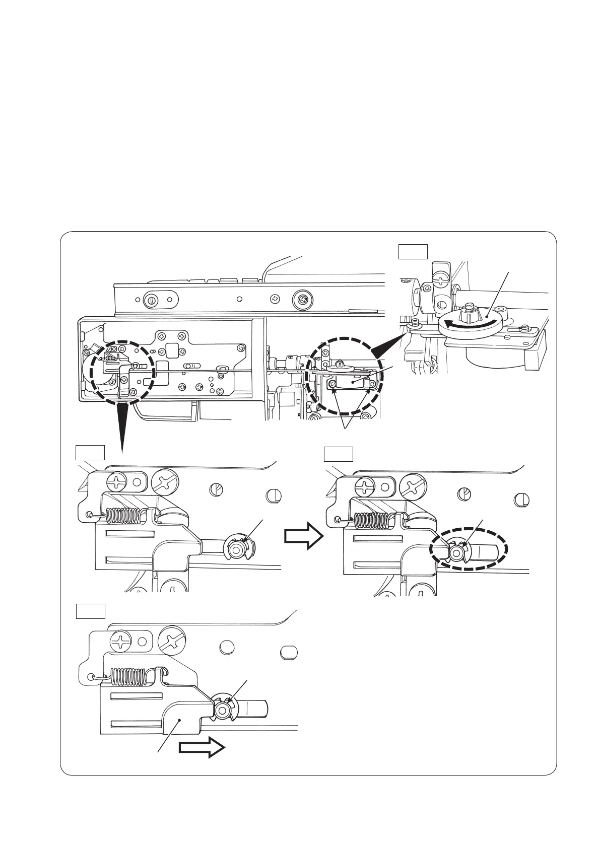
6-22 Position of the automatic DF motor
○
RemovethethebottomcoverA/Bandthebottomcoverofthefreearm.
Adjustmentprocedure
1. Turn DF cam gear
❶
in the direction of the arrow in Fig. 1 until it will go no further.
2. When DF operating part
❷
is at the position as shown in Fig. 2, turn the handwheel to check that the DF
operatingpartisbroughttotheposition(leftsideofthegroove)asshowninFig.3.
3. Loosen two setscrews
❸
oftheDFmotor.AdjustthelateralpositionofDFmotor
❹
. Then, tighten set-
screws
❸
to secure the DF motor.
Atthistime,adjustthepositionofDFdrivingpart
❺
byshiftingitinthedirectionofthearrowsothatitstip
slightly comes in contact with the DF operating part
❷
. (Fig.4)
Fig.1
Fig.2
Fig.3
Left side of the
groove
Fig.4
 Loading...