6.
DISASSEMBLING
&
ASSEMBLING
PROCEDURES
AND
PRECAUTIONS
Disassembling & Assembling Procedures
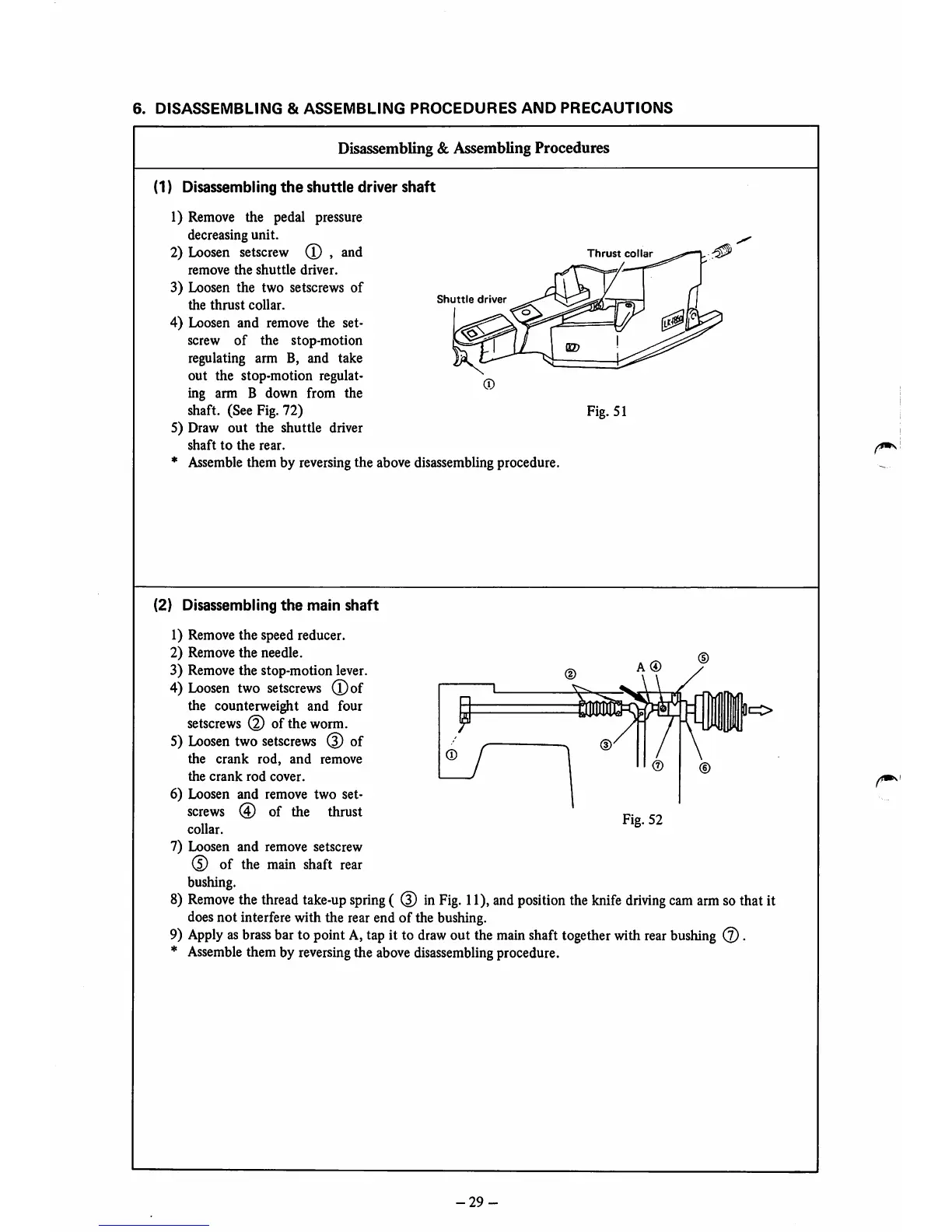
(1) Disassembling
the
shuttle
driver
shaft
1) Remove the pedal pressure
decreasing unit.
2)
Loosen
setscrew
(T)
,
and
remove
the
shuttle
driver.
3) Loosen the two setscrews of
the
thrust
collar.
4) Loosen and remove the set-
screw
of
the stop-motion
regulating arm B, and take
out
the stop-motion regulat
ing arm B down from the
shaft. (See Fig. 72)
5) Draw
out
the shuttle driver
shaft
to
the
rear.
* Assemble them by reversingthe above disassembling procedure
(2) Disassembling
the
main
shaft
1) Remove the speed reducer.
2) Remove the needle.
3) Remove the stop-motion lever.
4)
Loosen
two
setscrews
(Dof
the counterweight and four
setscrews
of
the
worm.
5)
Loosen
two
setscrews
(5) of
the
crank
rod,
and
remove
the
crank
rod
cover.
6) Loosen and remove two set-
screws
@ of the thrust
collar.
7) Loosen and remove setscrew
0 of the
main
shaft
rear
bushing.
Shuttle
driver
Thrust
collar
Fig. 51
DO
8)
Remove
the
thread
take-up
spring
( (3) in
Fig.
11),
and
position
the
knife
driving
cam
arm
sothat it
doesnot interfere with the rear end of the bushing.
9)
Apply
as
brass
barto pointA,tap it to
draw
out the
main
shaft
together
with
rear
bushing
(2).
*
Assemble
them by
reversing
the abovedisassembling procedure.
-29
 Loading...