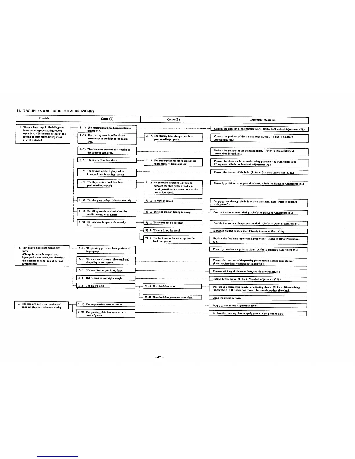
11.
TROUBLES
AND
CORRECTIVE
MEASURES
Trouble
1. Tlie machine stops in the idling area
between losv-specd
and
high-speed
operation. (The machine stops at the
second or third stitch (idlingarea)
after
it is
started.
2. The machine docs not run at higli
speed.
(Change between low-speed and
high-speed is
not
made,
and therefore
the
machine
does
not
run
at
normal
sewing
speed.)
3. Tliemachinekeepson runningand
does not stop in continuous sewing.
Cause (1)
1
-1)
The pressingplate has been positioned
improperly.
1
-2)
Tlie starting lever is pulled down
excessivelyto the high-speed idling
1
-3)
The
clearance
between
the
clutch
and
the
pulley
istoo
large.
—I
1-4)
The
safely
place
has
stuck.
—
1-5)
The tension of the high-speedor
losv-spced
belt
Ls
not
high
enough.
I 6) The stop-motion
hook
h-asbeen
positioned improperly.
I 8) The idling
area
is
reached
when
the
needle
penetrates
material.
I 9) Tile machine torque is abnormally
large.
2
-1)
The pressing plate has been po.sitioned
improperly.
2-
2)
The
clearance
between
the
clutch
and
the pulley is not
correct.
2-3)
The machinetorque is too large.
2 4) Belt tension is not high enough.
2-5)
The clutch slips.
3
-1)
The stop-motion lever has stuck.
3-2)
The pressingplate has worn or is in
want
of
grease.
Cause
(2)
2) -A Tlic starting leverstopper has been
positioned
improperly.
4)-A
Tlie .safetyplate has stuck against the
pedal
pressure
decreasing
unit.
6) A An
c.xcessive
clearance i.sprovided
lietwecn the
stop-motion
hook
and
the .stop-motion cam
when
the
machine
runs
at low speed.
7)-A
In
want
of grease
8) -A The stop-rootion timing is wrong.
19) A
The
worm
has
no
backlash.
H
TIic
crank
rod
ha.<
.ituck.
9) C Tlic feed cim roller .sticks against the
feedcam
groove.
5)-
A
The
clutch
ha.s
worn.
5) B Tlie clutch has grease on its surface.
47
Corrective
measures
1
Correct
the
position
of
tlie
prctsine
plate.
(Rcfci
lo
Standard
Adjustment
(5).)
Correct the position of the .startingicvetstopper. (Refer to Standard
Adjustment
(6).)
Reduce
the
number
of the
adjusting
shims.
(Referto
Disassembling
&
Assembling
Procedures.)
Correctthe
clearance
between
the
safety
plateand theworkclampfoot
lifting lever. (Refer to Standard Adjustment (7).)
Collect the tensionof the belt. (Referlo StandarilAdjustment(21).)
Correctly
positionthe
stop-motion
hook. (Refct to
Standurd
AdjuMmcnt
(3).I
Supply grease through the hole in the main shaft. (See "Parts to be rUlcd
with
grease".)
Correctthe
Mop-motion
timing. (Refctto Standard
Adjustment
(4).)
J 1
Provide
the
worm
with
a
proper
backlash.
(Refer
to
Other
Precautions
(4).)
] II
Move
the
orcilbting
rock
shaft
laterally
to
correct
the
sticking.
Replace the feed cam roller with a proper one. (Refer to Other Precautions
(5).)
Correctly
positionthe
pressing
plate. (Referto
Standard
Adjustment
IS).)
Correct the position of the
pressing
plateand the starting leverstopper.
(Refer
to
Standard
Adjustment
(5)and
(6).)
1
Remove
slicking
of
the
main
shaft,
shuttle
driver
shaft,
etc.
Correct Iwit tension. (Refer to Standard Adjustment (21).)
Increase
or
decrease
the
number
of
adjusting
shims.
(Referto
Disassembling
Procedures.) If this docs not correct the trouble, replacethe clutch.
Gcan
the
clutch
surface.
Supplygrease to the stop-motion lever.
Replace
the
pressing
plateorapply
grcaaie
to the
pressing
plate.
 Loading...