– 52 –
3. INSTALLATION OF THE OPTIONAL PARTS
(1) DL device (For the machine with thread trimmer only)
o Installing DL device (List A)
Part No. of DL22 Kit C for installation after mechanical
setup: 40025683
* Please order from us with the aforementioned part No.
(Applicable models: LU-1510N-7, LU-1511N-7, LU-1560N-
7, LU-1561N-7)
1. Remove window plate C and window plate packing C lo-
cated on the anti-operator’s side of the machine arm.
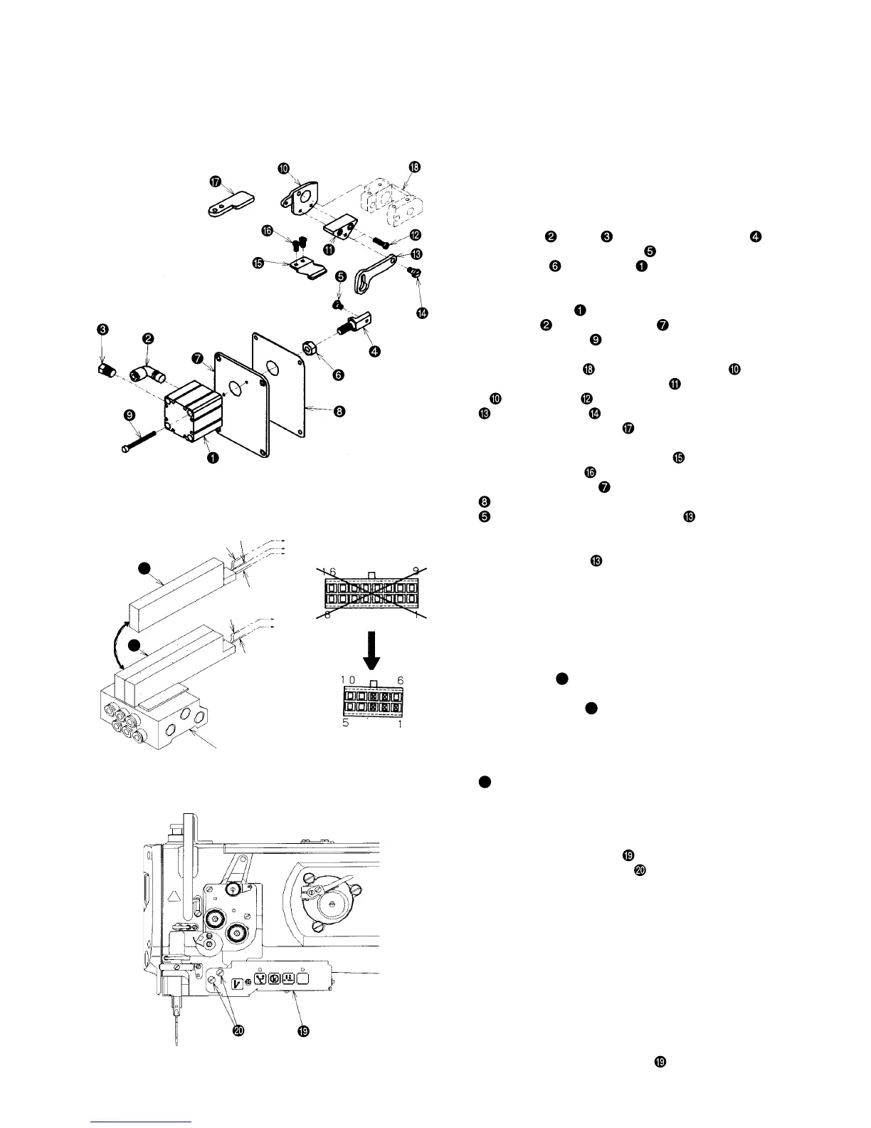
2. Attach elbow
, muffler , cylinder connecting screw ,
alternate vertical link hinge screw and cylinder connect-
ing screw nut to jig cylinder . (Assemble so that the
distance from the edge of cylinder connecting screw to the
end of cylinder shaft is 10 mm.)
3. Attach jig cylinder
which has been assembled at the
above step
. to window plate F and tighten it with
jig cylinder setscrew .
4. Remove the top feed stopper plate A attached to alternate
vertical change base
and install stopper plate B .
5. Tighten alternate vertical link spacer to stopper plate
B with setscrew and tighten alternate vertical link
with hinge screw .
6. Attach top feed stopper plate in the kit instead of the top
feed stopper plate attached to the machine arm.
7. Tighten alternate vertical link support
to the machine
arm with setscrews .
8. Install window plate F and window plate packing E
. At this time, enter alternate vertical link hinge screw
to the hole of alternate vertical link and attach it
to the machine arm.
(When the alternate vertical dial is set to the maximum,
alternate vertical link
comes out to the front and it is
easy to enter the screw in the hole.)
9. Change the automatic reverse feed device attached to
window plate C to window plate D.
10. Attach the window plate D and window plate packing B
with the window plate setscrew.
11. Re-adjust the respective timing adjustment referring to
this manual.
12. Solenoid valve
a
is attached to solenoid valve B (asm.)
(Part No.: GAKA2301BA0) presently used. Replace this valve
with solenoid valve D
A
.
(At that time, remove all pins from the 16-pin connector. This
treatment is needed when replacing a 16-pin connector with
a 10-pin connector.)
13. Caulk the female terminal at the cord tip of solenoid valve D
A
that has been replaced as per 12. above.
14. Insert the female terminal in the housing (10-pin
connector) (CN20) of the kit interior. Confirm the
inserting position before taking actions.
15. Remove the BT switch that is attached to the arm, and
attach 5-operation switch
of the kit interior to the
arm by means of setscrews
. At that time, remove
the BT switch pin from the 12-pin connector located
on sewing machine side.
16. Make a connection between the 16-pin connector of the 5-
operation switch and that of the relay cord connected to SC-
510.
17. Make a connection between the 12-pin connector attached
to the arm and that of the relay cord connected to SC-510.
18. Make a connection between the 10-pin connector of the
solenoid valve B (asm.) and that of the 5-operation switch.
19. Turn ON the power supply of SC-510.
20. Check whether the amount of alternate vertical movement
becomes maximum when the DL switch (second button
from left of the 5-operation switch
) is pressed.
o Installing the pneumatic components (List B)
o Installing the 5-operation switch (List C)
Red
Black
Solenoid valve B (asm.)
Red
CN20-8
CN20-3
CN20-1
a
A
CN20-7
CN20-2
CN20
Black
White
 Loading...