– 58 –
1. Remove the side plate located on the anti-operatorís side of the machine arm. (List of the parts to be removed)
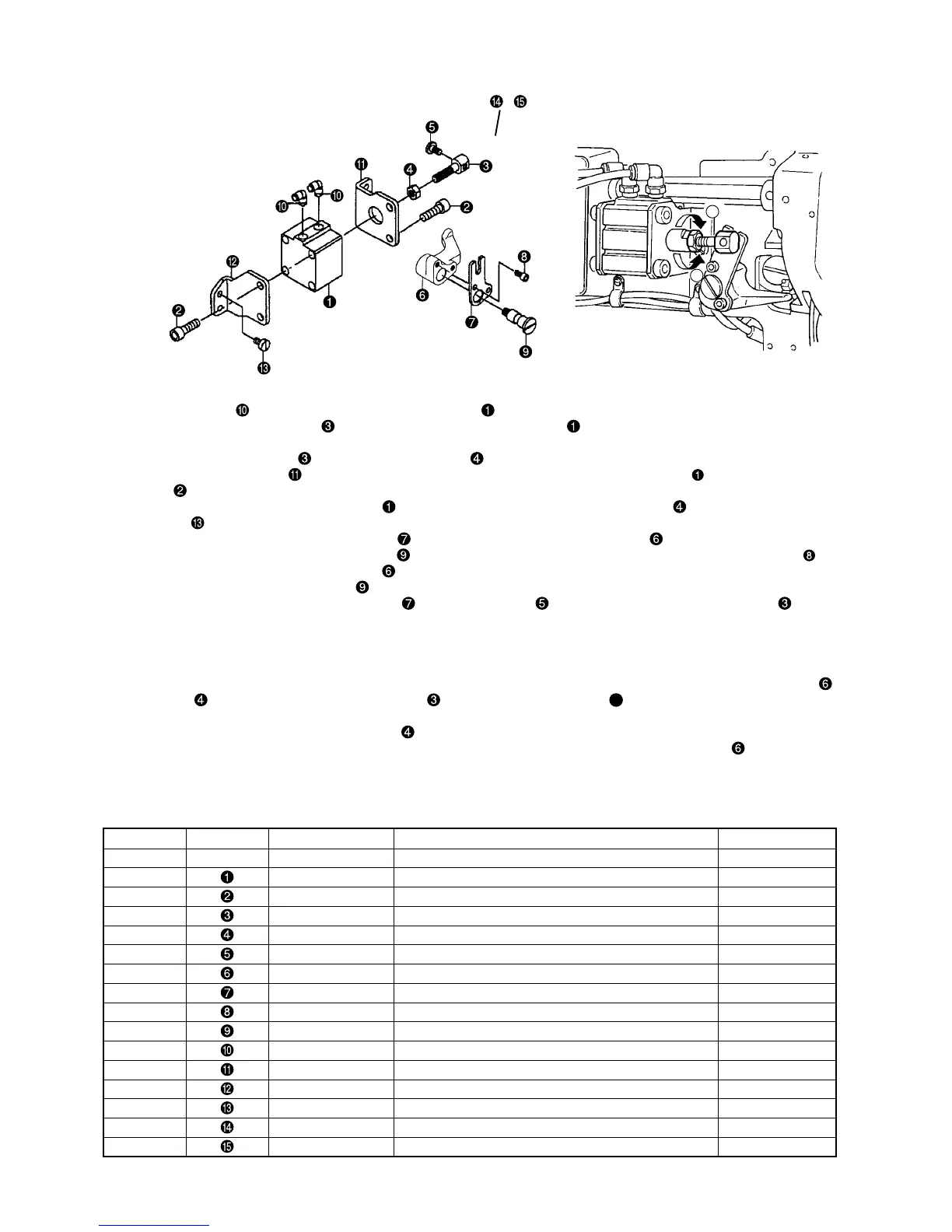
2. Install two elbows
to automatic presser foot lifter cylinder .
3. Install cylinder connecting screw to automatic presser foot lifter cylinder .
For the standard, adjust the distance from the end face of piston rod of automatic presser foot lifter cylinder 1 to the end face
of cylinder connecting screw
to 24 mm, and tighten nut .
4. Tighten cylinder stay, front and cylinder stay, rear !2 to automatic presser foot lifter cylinder with cylinder stay set-
screws .
5. Install automatic presser foot lifter cylinder
which has been assembled at the above step . to the machine arm with
setscrews .
6. Assemble automatic presser foot lifter lever B with automatic presser foot lifter lever A .
(Insert automatic presser foot lifter lever shaft
into the holes of both levers and tighten with hexagon headed bolt .)
7. Install automatic presser foot lifter lever A which has been assembled at the above step 6. to the machine arm with
automatic presser foot lifter lever shaft .
(Groove of automatic presser foot lifter lever B
enters hinge screw attached to cylinder connecting screw .)
8. Install pneumatic components.
9. Insert the air hose and check the operation.
When actuating the automatic presser foot lifter, make sure that the distance from the bottom face of the presser foot to the
top surface of the throat plate is 16 ± 0.5 mm.
When adjustment is required, remove automatic presser foot lifter lever shaft 9 and automatic presser foot lifter lever A
,
loosen nut
, and turn cylinder connecting screw . (Turning in the direction of
A
will decrease the distance, or in the
direction of B will increase it.)
After the completion of adjustment, tighten nut .
10. Make sure that a clearance of 0.5 to 1.5 mm is provided between automatic presser foot lifter lever A
and the thread
release supporting plate when the presser foot is lowered.
11. For the kit A (knee lifter switch), tighten presser foot lifter knee switch B (asm.) with the wood screws.
Note No. Part No. Name of part Q’ty
40025686 Automatic presser foot lifter (asm.) (1)
PA400150100 Automatic presser foot lifter cylinder 1
SM6082502TP Setscrew 4
21356506 Cylinder connecting screw 1
NM6080001SE Nut 1
SD0720331SP Hinge screw 1
21356605 Automatic presser foot lifter lever A 1
21356803 Automatic presser foot lifter lever B 1
SM6051002TP Hexagon bolt 2
21356704 Automatic presser foot lifter lever shaft 1
PJ304065102 Elbow 2
21356308 Cylinder stay, front 1
21356407 Cylinder stay, rear 1
SS6151040SP Setscrew 4
CM3002000B1 Caution seal for being caught (For domestic market) 1
CM300200001 Caution seal for injury to finger (For export) 1
Automatic presser foot lifter components (List A)
B
A
△
,
(5) Automatic presser foot lifter
1) Installing the automatic presser foot lifter (List A)
 Loading...