1-14 (No.MB385)
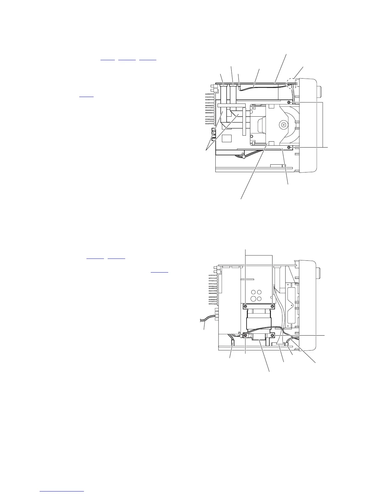
3.1.8 Removing the center chassis assembly
(See Fig.16)
• Remove the metal cover, tuner, video board and rear panel.
(1) From the top side of the main body, disconnect the card
wires from the connectors (CN11, CN511, CN513) on the
main body.
Reference:
When reassembly, pass the card wire through the sec-
tion f of the main board before connecting the card wire
to the connector CN11
.
(2) Remove the two screws P attaching the center chassis as-
sembly.
(3) Take out the center chassis assembly with the DVD mech-
anism assembly from the main body.
Fig.16
3.1.9 Removing the transformer board
(See Fig.17)
• Remove the metal cover, tuner, video board, rear panel and
center chassis assembly.
(1) From the top side of the main body, disconnect the wires
from the connectors (CN119
, CN250) on the transformer
board.
(2) Disconnect the parallel wire from the connector CN103 on
the transformer board.
(3) Remove the four screws Q attaching the transformer board
and take out the transformer board from the main board.
Fig.17
Main board
CN513
DVD mechanism assembly
CN11
CN511
Card wire
Card
wires
P
Center chassis assembly
f
CN250
Power
cord
Q
CN119
CN103
Parallel wire
Transformer board
Q
Q
 Loading...