(No.MB385)1-23
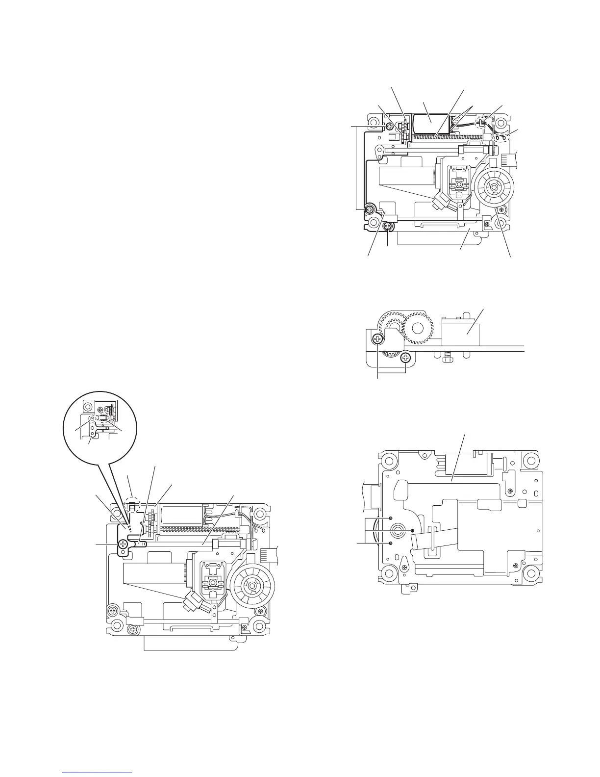
3.2.7 Removing the feed motor
(See Figs.10 to 12)
• Remove the traverse mechanism assembly.
(1) From the top side of the traverse mechanism assembly, re-
move the screw G attaching the plate and thrust spring.
(See Fig.10.)
(2) Remove the engagement section p attaching the plate to
the feed holder and remove the plate. (See Fig.10.)
(3) Remove the engagement sections (q, r), remove the thrust
spring. (See Fig.10.)
(4) Remove the wires from the soldered section s on the spin-
dle motor board. (See Fig.11.)
Reference:
When attaching the feed motor, pass the wire through
the section t on the spindle base. (See Fig.11.)
(5) Remove the feed holder, feed motor, lead screw, feed gear
E and feed gear M at the same time after removing the
three screws H attaching the feed holder. (See Fig.11.)
(6) From the side of the feed holder, remove the two screws J
attaching the feed motor. (See Fig.12.)
3.2.8 Removing the spindle motor board
(See Figs.11 and 13)
• Remove the traverse mechanism assembly and DVD module
board.
(1) From the top side of the traverse mechanism assembly, re-
move the wires from the soldered section s on the spindle
motor board. (See Fig.11.)
(2) From the bottom side of the traverse mechanism assem-
bly, remove the three screws K attaching the spindle motor
board. (See Fig.13.)
Fig.10
Fig.11
Fig.12
Fig.13
Thrust spring
Plate
G
p
Traverse mechanism assembly
q
r
Thrust spring
Feed holder
Spindle motor board
Spindle base
Feed holder
Feed gear E
Feed gear M
Feed motor
Lead screw
Wires
t
H
H
s
Feed holder
J
Traverse mechanism assembly
K
 Loading...