1-18 (No.MB385)
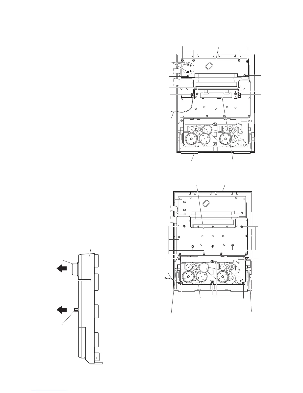
3.1.13 Removing the FL board
(See Figs.22 and 23)
• Remove the metal cover and front panel assembly.
(1) From the front side of the front panel assembly, pull the vol-
ume knob out of the front panel assembly. (See Fig.22.)
(2) From the inside of the front panel assembly, remove the six
screws T attaching the FL board. (See Fig.23.)
(3) Release the claws q in the direction of the arrow and take
out the FL board from the front panel assembly. (See
Fig.23.)
3.1.14 Removing the switch board
(See Figs.22 to 24)
• Remove the metal cover and front panel assembly.
(1) From the front side of the front panel assembly, pull the mi-
crophone knob out of the front panel assembly. (See
Fig.22.)
(2) From the inside of the front panel assembly, remove the
three screws U and screw U' attaching the stay bracket.
(See Fig.23.)
Reference:
When attaching the screw U', attach the earth wire with
it. (See Fig.23.)
(3) From the inside of the front panel assembly, remove the
eleven screws V attaching the switch board. (See Fig.24.)
(4) Take out the switch board from the front panel assembly.
3.1.15 Removing the cassette mechanism assembly
(See Fig.24)
• Remove the metal cover and front panel assembly.
(1) From the inside of the front panel assembly, remove the
three screws W, screw W' and two screws X attaching the
cassette mechanism assembly.
(2) Take out the cassette mechanism assembly from the front
panel assembly.
Reference:
• When attaching the screw W', attach the earth wire with it.
• When attaching the screws X, attach the swing cam (L)/(R)
with them.
Fig.22
Fig.23
Fig.24
Microphone knob
Volume knob
Front panel assembly
TT
T
U
T
FL board
q
Stay bracketFront panel assembly
U
U'
Earth wire
X
W
Front panel assembly
Swing cam (R)
Earth
wire
Swing cam (L)
Cassette mechanism
assembly
V
Switch board
X
W'
 Loading...