1-24 (No.MB385)
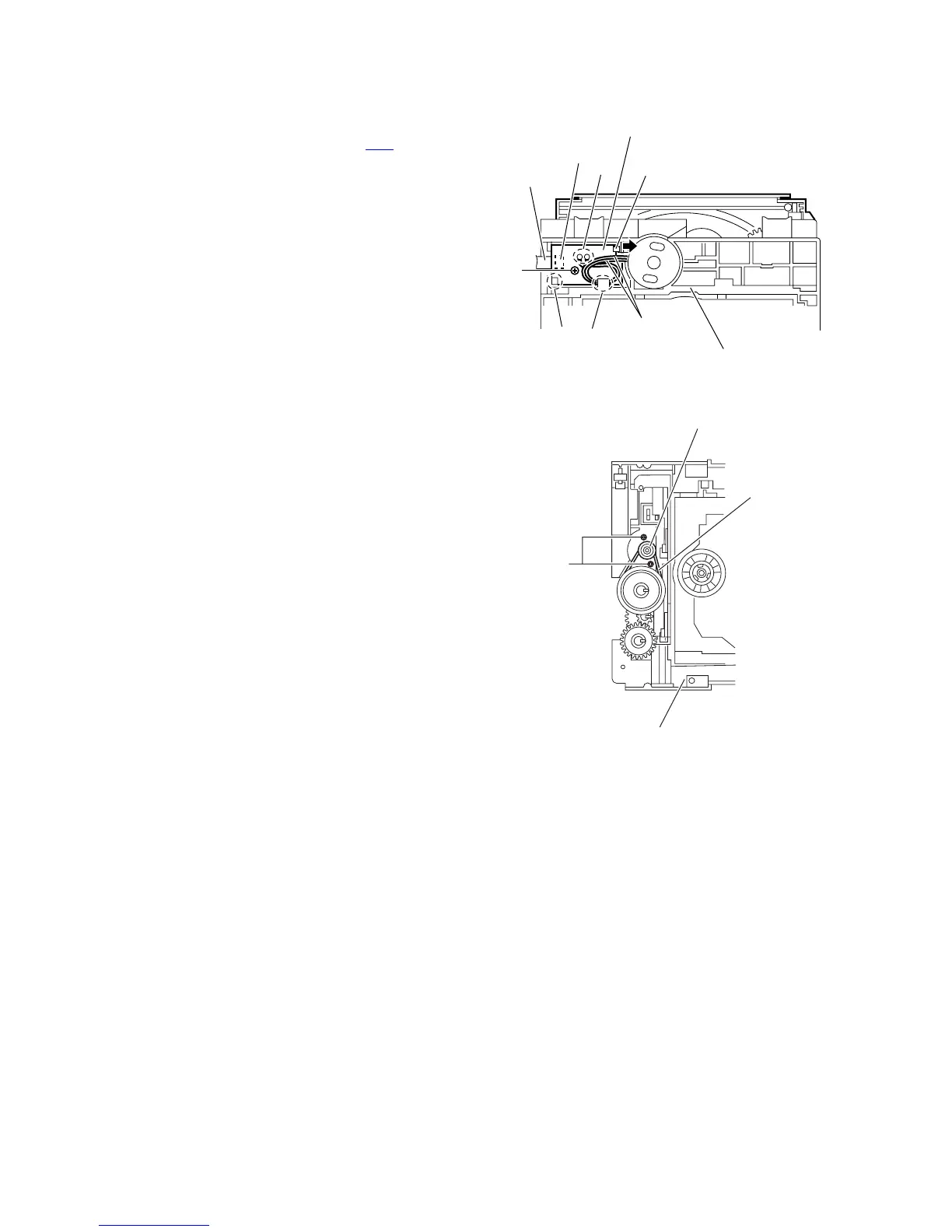
3.2.9 Removing the switch board
(See Fig.14.)
(1) From the bottom side of the DVD mechanism assembly, re-
move the screw L attaching the switch board.
(2) Disconnect the card wire from the connector CN1 on the
switch board.
(3) Remove the wires from the soldered section u on the
switch board.
(4) Lift the switch board while pressing the claw v of the DVD
mechanism assembly in the direction of the arrow and re-
move it from the section w.
Reference:
Put the wires on the section x after attaching the switch board
to the DVD mechanism assembly.
3.2.10 Removing the motor
(See Figs.14 and 15)
• Remove the clamper base and tray assembly.
(1) From the bottom side of the DVD mechanism assembly, re-
move the wires from the soldered section u on the switch
board. (See Fig.14.)
(2) From the top side of the DVD mechanism assembly, re-
move the belt from the motor pulley. (See Fig.15.)
Note:
Take care not to attach grease on the belt.
(3) Remove the two screws M attaching the motor to the DVD
mechanism assembly and take out the motor from the bot-
tom side of the DVD mechanism assembly. (See Fig.15.)
Reference:
Put the wires on the section x after attaching the motor to the
DVD mechanism assembly. (See Fig.14.)
Fig.14
Fig.15
Switch board
Wires
u
v
x
DVD mechanism assembly
L
CN1
w
Card wire
DVD mechanism assembly
M
Belt
Motor pulley
 Loading...