(No.MB368)1-11
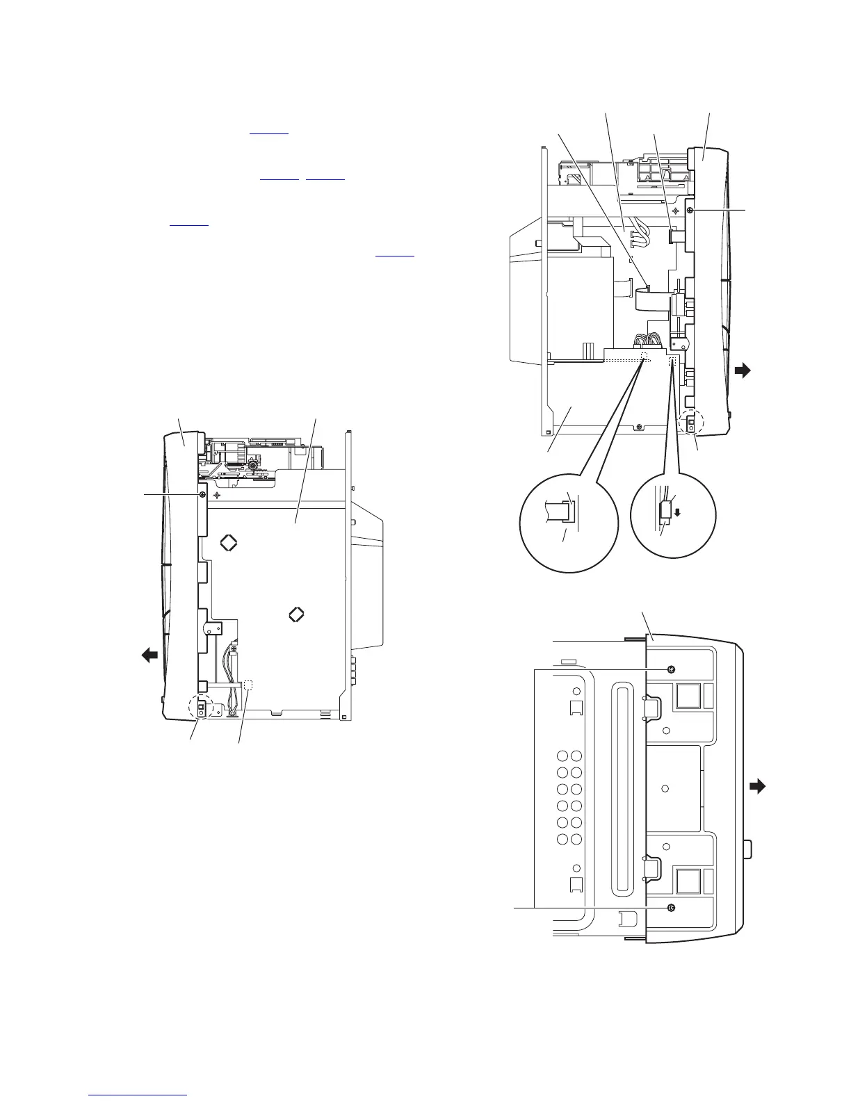
3.1.2 Removing the front panel assembly
(See Figs.4 to 6)
• Remove the metal cover.
(1) From the right side of the main body, disconnect the card
wire from the connectors CN740
on the reverse side of the
main board. (See Fig.4.)
(2) From the left side of the main body, disconnect the card
wires from the connectors (CN720
, CN730) on the forward
side of the main board. (See Fig.5.)
(3) Disconnect the parallel wire while releasing the lock of the
connector CN105
on the primary board in the direction of
the arrow. (See Fig.5.)
(4) Disconnect the parallel wire from the connector CN202
on
the bridge board. (See Fig.5.)
(5) From the both side of the main body, remove the two
screws C attaching the front panel assembly to the main
body. (See Figs.4 and 5.)
(6) From the bottom side of the main body, remove the two
screws D attaching the front panel assembly. (See Fig.6.)
(7) From the both side of the main body, release the claws a
and remove the front panel assembly from the main body
in the direction of the arrow. (See Figs.4 to 6.)
Fig.4
Fig.5
Fig.6
Front panel assembly Main board
CN740
a
C
CN730 CN720
Primary board
Front panel assemblyMain board
C
a
Bridge board
CN202
CN105
Lock
Front panel assembly
D
 Loading...