Country-
spec.
Settings
Men
u
leve
l
Display/
Setting
Action in this menu/meaning
Settling time
100 – 1200000 [ms]
Specifies the dynamic behaviour at change of active power set point. On
a voltage change, the active power is changed according a PT-1 charac-
teristic with a settling time equal to 5 Tau.
Note: The settling time is superimposed with the increase and decrease
gradient.
Number of nodes
2- 5
Power
0.0 -100.0 [%]
Voltage
0.0 -126.0 [%]
Up to 5 nodes configurable for voltage [V] and power [% Pref]. The
power-value of the first and the last value pair is also used as maximum,
minimum respectively active power value which is valid beyond the lim-
its of the characteristic.
Active curve
1 - 5
F Select the active curve.
NOTE:Up to 5 characteristic curves can be configured inde-
pendently and one of them can be activated for regulation
each time.
10.2.3 P(f)
P(f) Active power response to overfrequence
Feed-in inverters must assist with frequency stability in the grid. If the grid frequency leaves the normal
tolerance range (e.g. ±200 mHz), the grid is in a critical state. In the event of overfrequency, there is a
generation surplus, in the event of underfrequency, there is a generation deficit.
PV-Systems must adapt their active feed-in power in relation to the frequency deviation. In case of
overfrequency the adaption of power is defined by a maximum feed-in limit. The actual power of the
inverter may vary freely below this limit based on possible fluctuation of the available power or set
point, but will never increase above the absolute power limit.
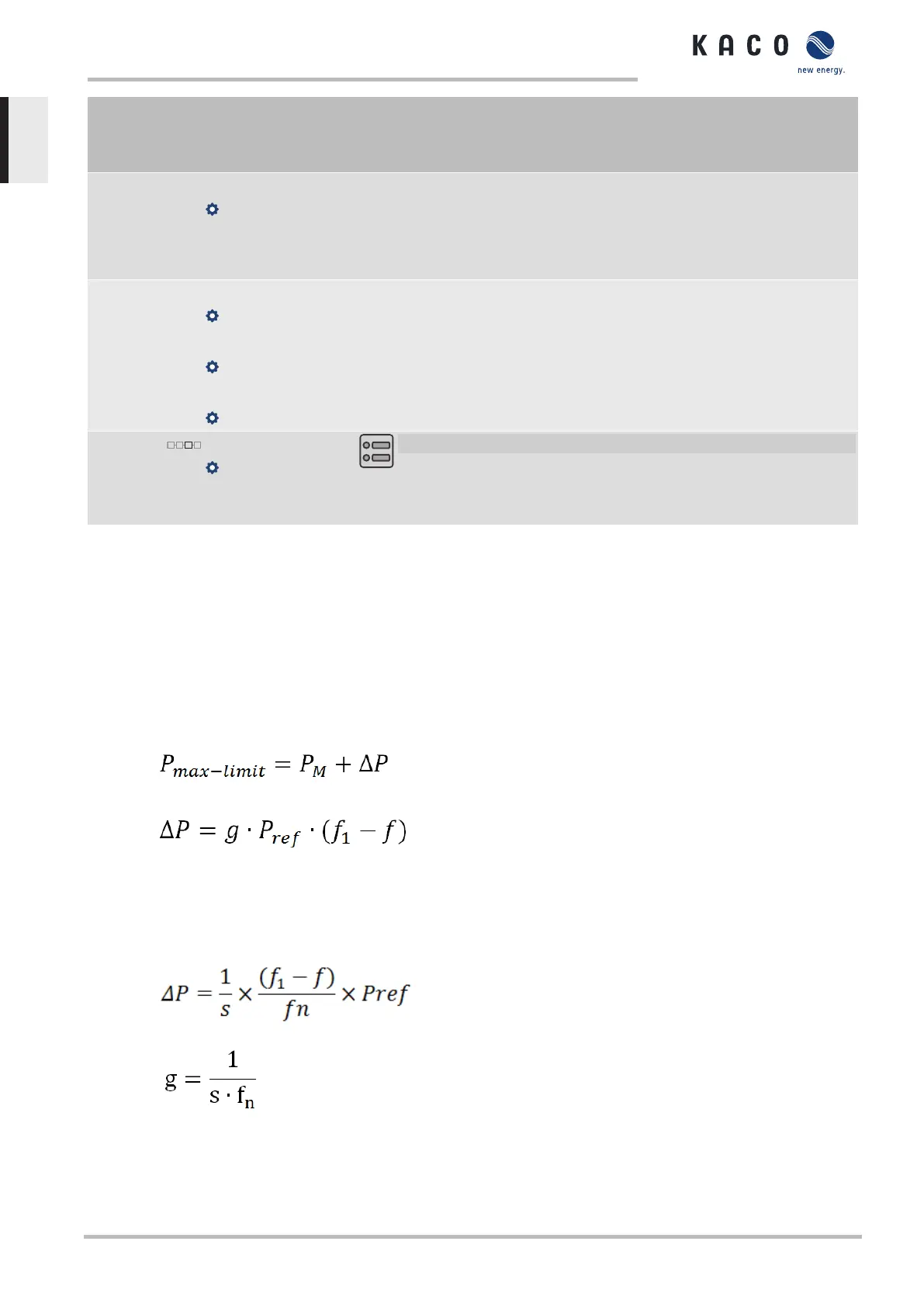
Fig.78: Equation 1
Fig.79: Equation 2
Equation 1 [See figure 78: Equation 1 [}Page84] defines the maximum limit with ΔP according to
Equation 2 [See figure 79: Equation 2 [}Page84], P
M
the actual power at the moment of activation
and P
ref
the reference power. In KACO PV inverters P
ref
is defined as P
M
, the actual power at the mo-
ment of activation. f is the actual frequency and f
1
is the activation threshold as configured.
Fig.80: Equation 3
Fig.81: Equation 4
In some standards the power adaption is not defined by a gradient – g but by a droop – s as in Equa-
tion 3 [See figure 80: Equation 3 [}Page84]. The droop s can be converted to a gradient g according
to Equation 4 [See figure 81: Equation 4 [}Page84].
10 | Specifications Manual
KACO blueplanet 87.0 TL3 KACO blueplanet 92.0 TL3 KACO blueplanet 105 TL3 KACO blueplanet 110 TL3
KACO blueplanet 125 TL3 KACO blueplanet 137 TL3 KACO blueplanet 150 TL3 KACO blueplanet 155 TL3
KACO blueplanet 165 TL3
Page 84
EN-US
 Loading...