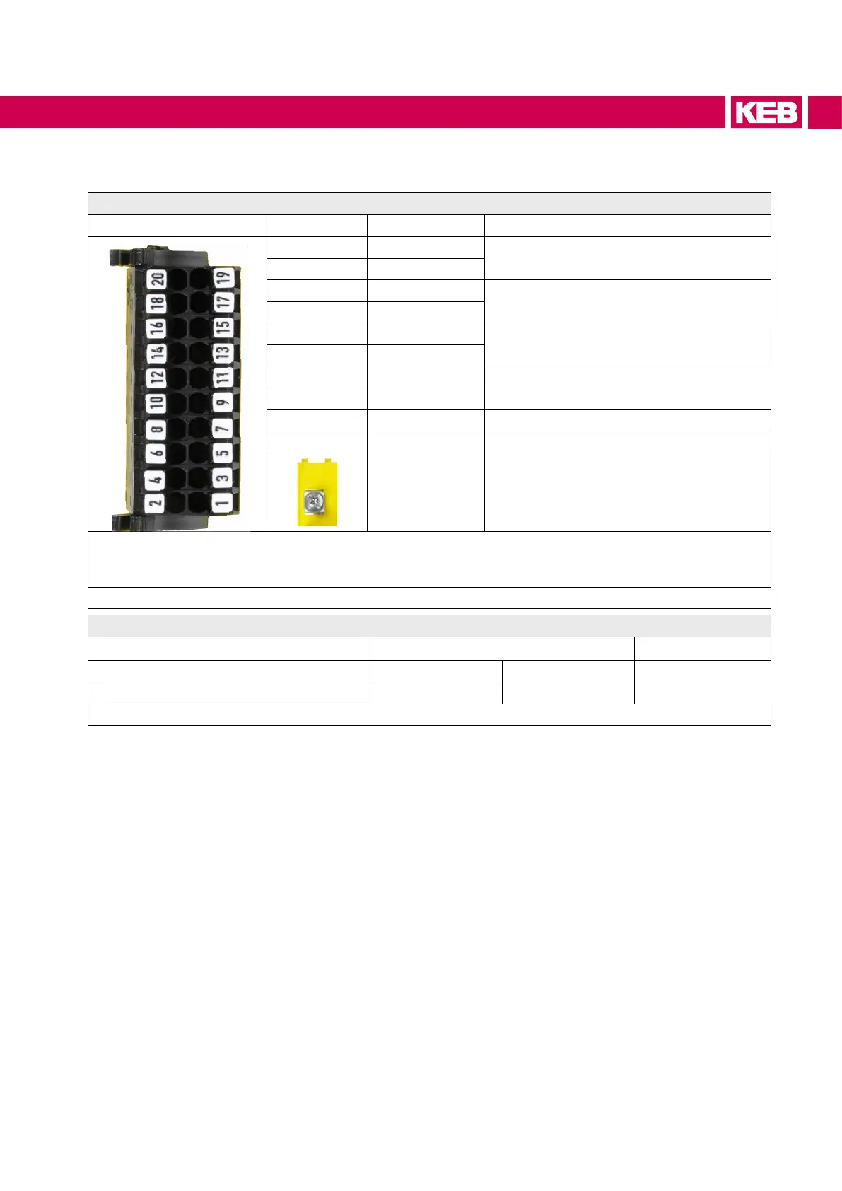
4 Description of the Terminals
Safety module type 1
Terminal
PIN Name Function
1 / 2 STO1+
Input
STO channel 1
3 / 4 STO1-
5 / 6 STO2+
Input
STO channel 2
7 / 8 STO2-
9 / 10 SBC1+
Input
SBC channel 1
11 /12 SBC1-
13 /14 SBC2+
Input
SBC channel 2
15 / 16 SBC2-
17 / 18 Status STO Output STO
19 / 20 Status SBC Output SBC
PE
For H6 drive modules:
Earth, make sure to connect the mains
earth !
The individual channels are designed potential-free, so 24V and 0V can be connected. The inputs are de-
signed by way that safety switchgear units with test pulses (OSSD signals) can be connected. The signals
arenotevaluated,theyareonlyltered.TheOSSDtestintervalislimitedto10ms.
Figure 1: Description of the Terminals
Terminal cross-section Stripping length
Strandedwire(rigidlyandexibly) 0.14…1.5 mm²
26-18 AWG 12 mm
Ferrule plastic collar 0.14…1 mm²
Table 6: Mechanical specication of terminal strip X2B
21
DESCRIPTION OF THE TERMINALS
 Loading...


