7.2 Direct switching off with emergency stop switch and monitoring of the wiring
U V W PE
M
X1A
B+ B- T1 T2
X4BX4A X4C
STO1+
STO1-
STO2+
STO2-
SBC1+
SBC1-
SBC2+
SBC2-
Status STO
Status SBC
+ -
24Vdc
1
2
3
4
5
6
7
8
9
10
11
12
13
14
15
16
X2A
Safety Circuit
Terminal strip X2B
Module type 1
Control circuit
Power circuit
Diagnosis
Field bus Field bus
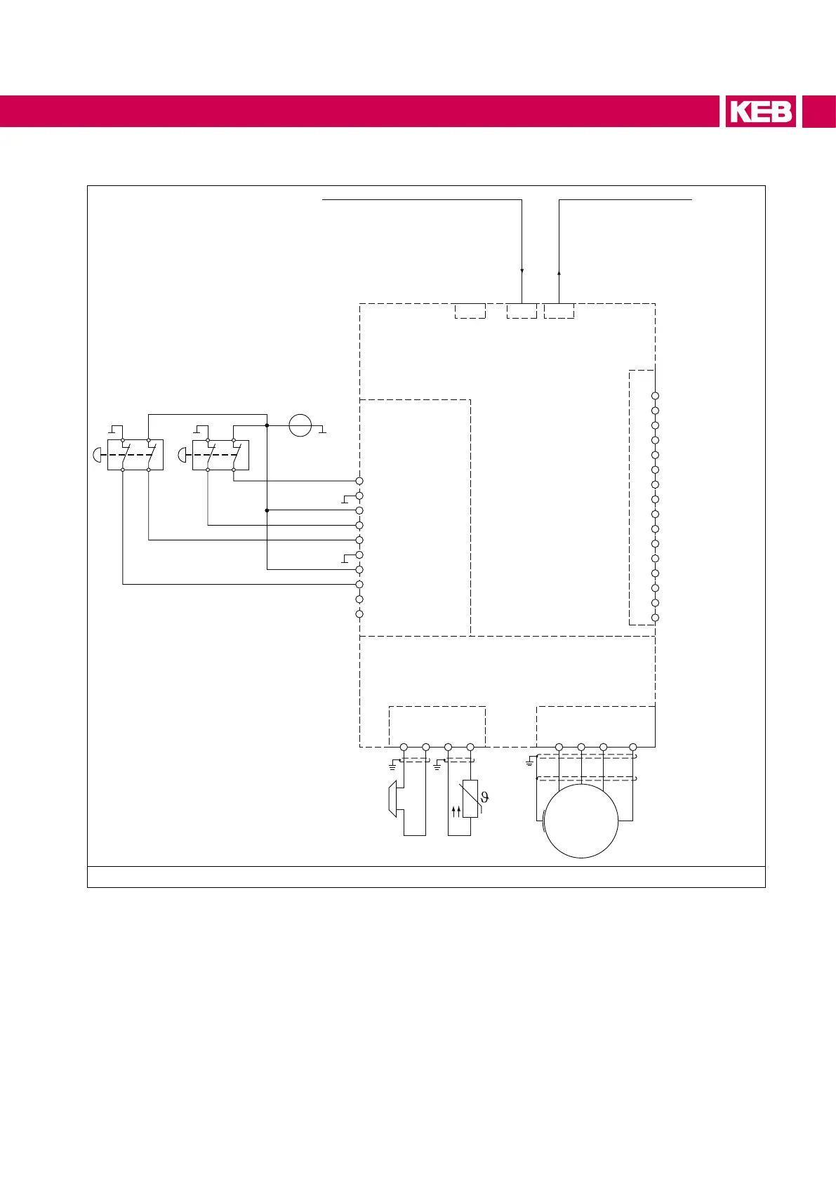
Figure 3: Direct switching off with emergency stop switch and monitoring of the wiring
The displayed circuit shows wiring errors in the area of the emergency stop unit and supply line. A
possible short circuit on the primary side of the emergency stop switchgear (mass and 24 Vdc) and a
short circuit on the secondary side of the unit or within the wiring leads either directly or with closed
contacts to a short circuit of the supply, whereby a series-connected 24V fuse triggers.
Besides the two displayed applications with an emergency stop switchgear, other sensors (like door
switches etc.) can be used similarly.
31
 Loading...


