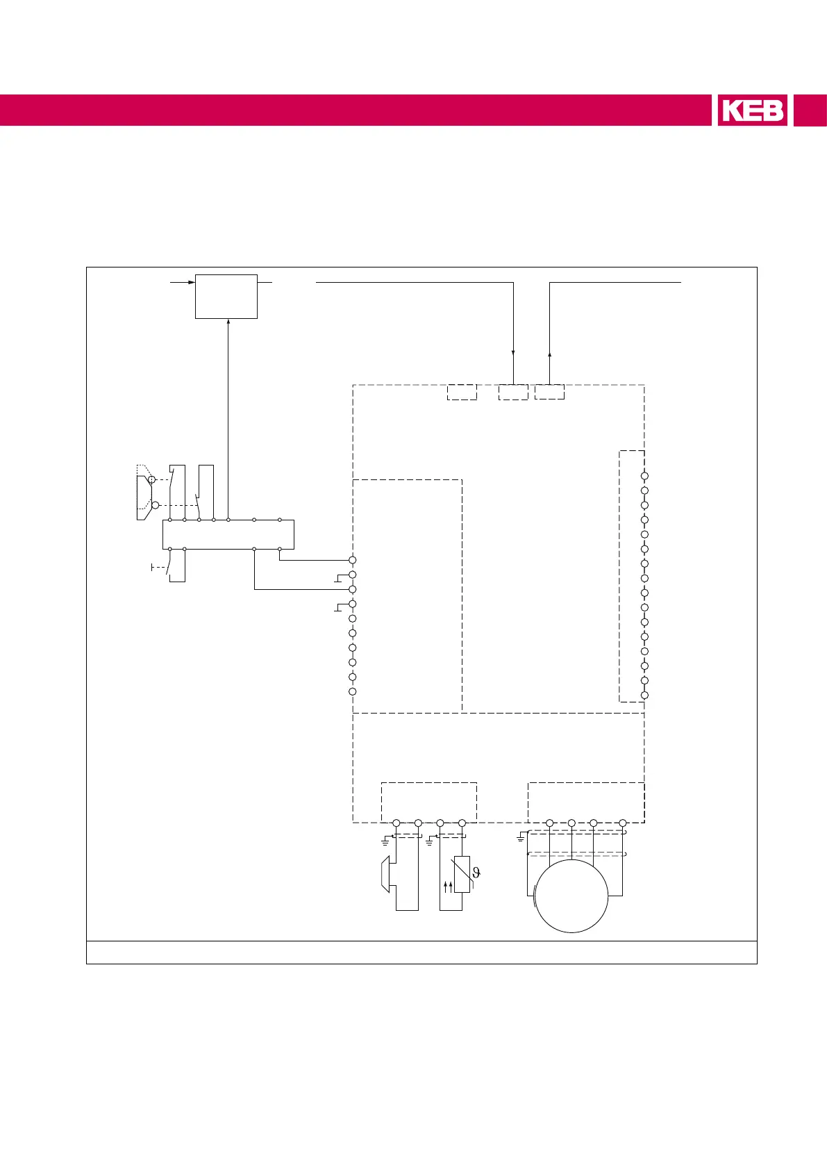
7.4 Wiring SS1
At tripping SS1 (Safe Stop 1) the drive is only disconnected from supply when it has reached a stand-
still [IEC 61800-5-2]. The stop mode is not directly requested, but the maximum time until reaching
the standstill is estimated. This period is loaded in a safe time relay, which disconnects the drive
nallyfromsupply.
U V W PE
M
X1A
B+ B- T1 T2
X4BX4A X4C
STO1+
STO1-
STO2+
STO2-
SBC1+
SBC1-
SBC2+
SBC2-
Status STO
Status SBC
1
2
3
4
5
6
7
8
9
10
11
12
13
14
15
16
X2A
S1 S2
Motion
Control
Field bus Field bus
Diagnosis
Control circuit
Safety circuit
Terminal strip X2B
Module type 1
Power circuit
Safety device
Acknowledgment
open
closed
Figure 5: Wiring SS1
By activation of the emergency stop unit the master motion control is instructed via an output to stop
the drive with a deceleration ramp. Simultaneously the expiration of the safe time occurs in the safety
module. After expiration of the safe period the control signals STO1+ und STO2+ are removed and
thus the energy supply of the drive is disconnected.
33
 Loading...


